Chapter 5
Designing Your Network
Have you ever tried to make a cell-phone call in an elevator? Were you shocked when the call dropped in the middle? Some people get annoyed when that happens. But others plan ahead. They know the call will drop due to the lack of reception, so they end the call before they step into the elevator and continue it when they get out. That is called proper planning.
We won't go into the reasons why cell-phone coverage is bad in general or why you have to hold your phone a certain way (sorry, iPhone) when you talk. What we'll examine in this chapter are the factors you need to take into account when designing the infrastructure for virtualization. We guarantee that if your servers go down due to a network outage resulting from bad planning, more than one person will be annoyed!
The topics we'll discuss in this chapter include
- Redundancy (at all levels)
- Security (this time, it's moved higher in the list)
- Networking considerations for the different vSphere components (HA, IP storage, FT, and so on)
- Sizing: which NICs to use for which purpose
- Virtual switches
- Naming conventions
- Design scenarios
Examining Key Network Components
As we've done in other chapters, we'll begin by first reviewing the major components in any network design. Although you're probably familiar with many, if not all, of these components, reviewing them establishes a baseline knowledge level on which we'll build throughout the rest of the chapter.
Ready? Let's start with the most visible (both literally and figuratively) component, the physical connectivity.
Physical Connectivity
Naturally, a network isn't a network without all the Layer 1 stuff (the first layer in the Open Systems Interconnect [OSI] model, the physical layer). A number of items are important in this layer:
Traffic patterns and traffic types are also components in the network design. Let's take a closer look at some of the network traffic types you can expect to see in a typical vSphere deployment.
Network Traffic Types
Unlike a nonvirtualized datacenter, virtualization introduces some new and additional types of traffic to consider when creating a network design. In this section, we'll examine the three major traffic types:
- Management traffic
- VMkernel traffic
- Virtual machine (VM) traffic
Let's start with management traffic.
Management Traffic
The management network is the lifeline into your ESXi host. If that lifeline goes down, you can't remotely manage that host. The host will think it has lost connectivity and—depending on the configuration of vSphere HA—may power down all the VMs it has running. The other hosts in the cluster may think the host is down and try to restart the VMs that were running. In a nutshell, bad things happen. Clearly, management traffic is pretty important, and later in this chapter (in the “Availability” section) we'll discuss ways to ensure that you don't lose management connectivity to your ESXi hosts.
VMkernel Traffic
Both management traffic and VMkernel traffic are new to a virtualized environment; that is, there is no nonvirtualized equivalent to these types of traffic. We use the term VMkernel traffic to refer to traffic generated by the ESXi hypervisor and not by VMs hosted by the hypervisor. Technically, this includes management traffic as well; however, given the importance of management traffic we felt it deserved its own section. In this section, we're referring to the other kinds of traffic generated by the hypervisor: vMotion, fault tolerance (FT), and IP-based storage.
Although all these traffic types are generated by the hypervisor, each has its own characteristics and considerations. For example, providing redundancy for vMotion traffic is handled differently than for IP-based storage. In fact, providing redundancy for iSCSI is different than providing redundancy for NFS, so there are key differences even within these different traffic types. As you integrate or incorporate these traffic types into your vSphere design, each will have a different impact on the design for which you'll need to account.
Now let's turn our attention to the third and final traffic type: traffic generated by VMs.
Virtual Machine Traffic
In addition to traffic generated by the hypervisor, you need to account for traffic generated by the VMs hosted by the hypervisor. Depending on the workloads that are deployed in the vSphere environment, this could be almost any type of traffic—from remote desktop protocols (like RDP, HDX, PCoIP) to file transfer (FTP, SFTP, SMB, NFS) to application-specific protocols (MS SQL Server, Oracle, SAP, HTTP, email, calendaring).
One thing that can sometimes trip up vSphere architects is differentiating between hypervisor-generated NFS/iSCSI traffic and VM-generated NFS/iSCSI traffic. It's important to note that steps taken to provide security and redundancy for hypervisor-generated IP-based storage traffic won't necessarily apply to VM-generated IP-based storage traffic. These traffic types originate from different sources and therefore typically need to be handled separately.
The last network component we'll discuss before exploring the factors influencing the network design is the software component.
Software Components
In addition to physical components discussed earlier—like cabling and physical switches—some significant software components make up a vSphere network design. The software components that probably jump to mind immediately are VMware's software-based switches (softswitches) in the hypervisor, but you'll also want to ensure that you consider some other important software components:
- Potential third-party softswitches, like the Cisco Nexus 1000v or the IBM DVS 5000v
- Virtual NICs (vNICs) in the guest OS instances
- Virtual firewalls, like vShield App, vShield Edge, or Cisco ASA 1000v
- Virtual load balancers or network address translators, like vShield Edge
Not all of these components will be present in every design, but where they're present or are needed—as dictated by the functional requirements—you'll need to account for the impact of their presence in your design. Later in this chapter, in the section “vSwitches and Distributed vSwitches,” we'll discuss some design considerations around the use of the VMware-supplied softswitches. In Chapter 12, “vCloud Design,” we'll provide some design considerations particular to vCloud Director, which typically will include vShield Edge as a key network design component.
In the next section, we transition from examining the network components to exploring some of the various factors that will influence your network design.
Exploring Factors Influencing the Network Design
In the previous section, we reviewed some of the key components of a vSphere network design. In this section, we'll explore some of the major factors influencing how you, the vSphere architect, should assemble these components to create the network design. In the next section (“Crafting the Network Design”), we'll discuss specific ways in which you can build a vSphere network design according to the five principles of design: availability, manageability, performance, recoverability, and security (AMPRS).
The factors influencing the network design that we'll discuss in this section include
- Physical switch support
- vSwitches and distributed vSwitches
- 10 Gigabit (Gb) Ethernet
- Single Root I/O Virtualization (SR-IOV) and DirectPath I/O
- Server architecture
This isn't a comprehensive list of all the potential factors that will influence your network design, but it should be enough to get you thinking about how various items can affect and/or influence the network design. Let's start with physical switch support.
Physical Switch Support
The features, capabilities, and protocols supported by the physical switches you incorporate into your design will, quite expectedly, play a significant role in shaping your vSphere network design. Some of the more significant areas of support about which you should be aware include
- Link aggregation
- Private VLANs (PVLANs)
- Jumbo frames
In addition, we'll discuss the impact of 10Gb Ethernet in the section “10Gb Ethernet”).
Let's start with a more in-depth look at link aggregation.
Link Aggregation
The vast majority of managed datacenter switches support link aggregation, so you might be wondering why link aggregation has its own section. Well, there are some key considerations around link aggregation that you'll want to address in your design. For example, you might want to ask yourself these sorts of questions about the link-aggregation support in your physical switches:
- Do the switches support any form of multiswitch link aggregation?
- What types of link aggregation does the switch support?
- What link-aggregation protocols are supported, if any?
- What load-balancing mechanisms are supported for placing traffic on the links in the aggregate?
The answers to these questions can have a dramatic impact on your vSphere network design. To understand why, however, we first need to ensure that everyone understands the basics of link aggregation.
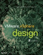
Link aggregation is a mechanism whereby two devices on a network—these could be two switches, or an end-host and a switch—agree to treat multiple physical links as if they were a single logical link. For example, you could configure two switches in the network to communicate with each other over four physical links, and use link aggregation to have the switches treat those four physical links as a single logical link. Similarly, you could configure an end-host (like an ESXi host) to communicate with a switch over four physical links, and the two systems could agree to treat those four physical links as a single logical link.
What does this buy you? Well, for starters, it allows the two devices to potentially use multiple physical links without worrying about Spanning Tree Protocol (STP) blocking some of the links to prevent bridging loops. (Note that link aggregation isn't the only way to work around this potential STP issue.) Using link aggregation also helps provide redundancy; the logical link remains up as long as at least one physical link in the link aggregate remains up.
Link aggregation can be a pretty handy technology, but it does have its limitations and considerations. Let's take a look at some of these:
Figure 5.1 Link aggregation without MLAG can't offer full redundancy.
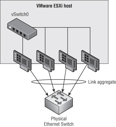
Figure 5.2 MLAG support offers both link redundancy and switch redundancy.
Whereas link aggregation serves to combine physical links together as logical links, sometimes vSphere architects need to provide a greater degree of separation between certain types of traffic. This is where VLANs and PVLANs can be helpful.
VLANs and Private VLANs
You're probably already familiar with the concept of VLANs, which allows users to logically subdivide physical network segments into separate broadcast domains. Although it isn't required, VLANs are typically associated with an IP subnet so that each VLAN = an IP subnet. For systems in different VLANs to communicate, they must pass their traffic through a Layer 3 device (a router).
By and large, VLANs are pretty well understood, and therefore the potential impacts of using VLANs in a vSphere environment are also pretty well understood. However, we want to point out a few things that are important to note:
- Many physical switches must be specifically configured to treat a link as a VLAN trunk (a link that will pass VLAN tags to connected systems). If you don't configure the links going to your vSphere hosts as VLAN trunks, then VLANs just won't work.
- Most VLAN implementations offer a single VLAN that doesn't carry any VLAN tags (even across a VLAN trunk). Depending on the vendor, this VLAN might be referred to as the native VLAN or the untagged VLAN. Regardless of what it's called, any vSphere port groups that should receive traffic for this particular VLAN shouldn't have a VLAN ID specified. It makes sense, if you stop to think about it (it is the untagged VLAN, after all).
- Building on the idea of the native VLAN (also called the untagged VLAN), it's also important to note that many switches can have different native VLANs on each port. This could create unpredictable results, so be sure to consistently assign the native/untagged VLAN across all switch ports in order to get consistent connectivity results.
- Different switch implementations support different ranges for VLAN IDs. Although the VLAN specification calls for VLAN IDs all the way up to 4094, some switches might not support that broad a range. Be sure your physical switches will provide the necessary VLAN ID support end-to-end, or your design's connectivity could be compromised.
- Because VLANs require a Layer 3 router to pass traffic from one VLAN to another, be sure to keep this in mind when evaluating availability and performance. (For example—have you provided any form of redundancy for the Layer 3 router that connects your VLANs? What if it goes down? What will happen to your vSphere environment?)
Although VLANs are fairly widely deployed, a related technology isn't quite so pervasive. Private VLANs (PVLANs) are related to VLANs but share some unique advantages over “regular” VLANs. For example, VLANs are typically associated with an IP subnet, and there is no easy way to restrict communications in a given VLAN/subnet.
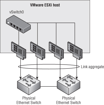
PVLANs, on the other hand, enable users to restrict communication between VMs on the same VLAN or network segment, significantly reducing the number of subnets needed for certain network configurations. PVLANs add a further segmentation of a logical broadcast domain to create private groups. Private in this case means that hosts in the same PVLAN can't be seen by the others, except those selected in a promiscuous PVLAN. (We haven't introduced the term promiscuous yet; hang tight for a second and we'll explain what that means in the context of a private VLAN.)
A PVLAN is divided into these two groups:
Figure 5.3 shows the connectivity among these three groups.
Figure 5.3 Systems in a PVLAN can only communicate with certain other nodes.
Although we haven't explicitly stated it yet, if you want to use PVLANs in your environment, you'll need physical switch support. Not all physical switches support PVLANs, so be sure to verify PVLAN support when selecting the switches for your vSphere design. Without physical switches that support PVLANs, traffic between PVLAN-configured ESXi hosts simply won't work. Another feature that is dependent on physical switch support, like PVLANs, is jumbo frames.
Jumbo Frames
The term jumbo frames means that the size of the largest Ethernet frame passed between one device and another on the Ethernet network is larger than the default of 1500 bytes. Jumbo frames are often set to 9000 bytes, the maximum available for a variety of Ethernet equipment, although this is by no means a ratified standard across vendors and network hosts. ESXi supports jumbo frames out of the box, but jumbo frames aren't enabled by default. The same is also true for many physical network switches: many of them support jumbo frames, but jumbo frames aren't configured by default.
The potential benefit of jumbo frames is that larger frames represent less overhead on the wire and less processing required at each end to segment and reconstruct Ethernet frames into the TCP/IP packets used by network protocols. Even though enhancements in the ESXi network stack keep reducing the CPU cycles needed to deal with jumbo frames, they're still often configured to extract even the slightest improvement in performance. You should always test your specific workloads and environment to see if the use of jumbo frames will give you added value and performance.
You must do two important things when working with jumbo frames:
vicfg-vswitch.pl --config c:usersadministratorvcli.txt
--vihost esxi51-01.design.local -a vSwitch1 -m 9000
vicfg-vmknic --config /home/admin/vcli.txt -a -i 192.168.1.9 -n 255.255.255.0
VMKernel -m 9000
With the release of vSphere 5.0, VMware simply added a GUI option for specifying the MTU. This GUI option is present for vSwitches, dvSwitches, and VMkernel ports. You can't specify the MTU when creating these objects (it's not included in the wizard), but you can easily edit the MTU after the fact to enable jumbo frames.
We've discussed the physical switches and their support in the role of the network design, but it's time to shift gears and focus on the virtual side of the network with a discussion of vSwitches and distributed vSwitches. This is the topic of the next section.
vSwitches and Distributed vSwitches
Before virtualization, the access-layer switches were the “last mile” of the network. Now that virtualization has (rightfully) entrenched itself in the datacenter, the last mile has moved into our servers. VMware's softswitches are now the last hop before hitting servers, applications, and workloads. VMware has two types of softswitches:
- The vSphere standard switch, also known as the vSwitch
- The vSphere distributed switch, more commonly known as the distributed vSwitch or the dvSwitch
Each type of virtual switch has its own strengths and weaknesses. One key factor in favor of the vSwitch is that vSwitches are available in every ESXi version from the vSphere hypervisor (free ESXi) all the way up to vSphere Enterprise Plus. dvSwitches, on the other hand, are only available on vSphere Enterprise Plus.
That distinction aside, let's start by comparing vSwitches to dvSwitches. The following features are available on both types of virtual switches:
- Can forward L2 frames
- Can segment traffic into VLANs
- Can use and understand 802.1q VLAN encapsulation
- Can have more than one uplink (NIC teaming)
- Can have traffic shaping for the outbound (TX egress) traffic
The following limitations or restrictions are also applicable to both types of virtual switches:
- Won't forward packets received on one uplink out another uplink (prevents bridging loops)
- Only supports IP hashing algorithms for link aggregation
The following features are available only on a dvSwitch:
- Can shape inbound (RX ingress) traffic
- Has a central unified management interface through vCenter
- Supports PVLANs
- Supports LACP for dynamic link aggregation configuration
- Supports load-based NIC teaming
- Uses persistent network statistics (sometimes referred to as network vMotion)
- As of vSphere 5.1, the ability to import/export VDS configuration
In this section, we're not going to dive deep into all these features; instead, we'll focus on how the differences between vSwitches and dvSwitches will impact your vSphere design. Specifically, we'll focus our discussion around two key topics:
- Centralized management
- vCenter Server as the control plane
Centralized Management
The larger your environment grows, the more dynamic it becomes, and the harder it gets to manage the network configuration and keep it consistent across all the hosts in your cluster. Consistency across the network configuration is important because a lack of consistency makes troubleshooting difficult and can introduce unexpected results. For example, a mismatched VLAN configuration between two hosts can result in VMs “dropping off the network” after a migration. As vSphere environments continue to scale, this challenge won't go away.
The dvSwitch helps address this challenge by treating the network as an aggregated resource. Individual, host-level vSwitches are abstracted into a single large dvSwitch that spans multiple hosts at the datacenter level. Port groups become distributed virtual port groups (dvPort groups) that span multiple hosts and ensure configuration consistency for VMs and virtual ports necessary for such functions as vMotion and network storage. The end result is reduced management overhead and improved consistency for network configuration.
Whereas the control plane for a vSwitch was found in an ESXi host, the control plane for a dvSwitch resides in vCenter Server. Moving the control plane into this one centralized place is what enables dvSwitches to provide the centralized management we've been discussing so far. (Although the control plane is centralized in vCenter Server, the switching plane/data plane is still locally situated in each ESXi host.) However, centralizing the control plane in vCenter Server is not without some concerns—and we'll discuss these concerns in the next section.
vCenter Server as the Control Plane
Putting the control plane for the dvSwitch into vCenter Server impacts your design in a number of ways. Let's talk about some of the potential ramifications you'll want to be sure to consider:
Aside from these considerations, the primary determinant of whether you should use a vSwitch or a dvSwitch really comes back to—you guessed it—the functional requirements. Does your design need a feature or function that is only supported by a dvSwitch? Then incorporate the dvSwitch into your design, accounting for the design impacts along the way. The same goes for using only vSwitches, using third-party virtual switches, or any combination of these.
In addition to virtual switches, another factor that will affect your network design is the use of IP-based storage, as well as the type of IP-based storage. The next section explores this factor in greater detail.
IP-Based Storage
For the most part, the type of network traffic isn't nearly as important as the volume (in megabits or gigabits per second), performance (in latency), or security requirements. As the saying goes, “There's an exception for every rule,” and it's true here as well. IP-based storage—specifically, the use of NFS and iSCSI by ESXi—has some specific considerations that could impact your network. Recall from our earlier discussion that NFS and iSCSI from the hypervisor are different than NFS and iSCSI from a guest VM, and that statement is applicable here as well. In this section, we'll focus specifically on IP-based storage being used by the hypervisor.
Although both NFS and iSCSI fall into the category of IP-based storage, the way in which these protocols operate is very different, so we need to discuss them differently. Let's start with iSCSI.
iSCSI
One of the key differences between iSCSI and NFS lies in how iSCSI and NFS handle multipathing. Multipathing—which we'll discuss in greater detail in Chapter 6, “Storage”—is the feature whereby the hypervisor can understand and potentially use multiple paths to a single datastore. iSCSI, as a block protocol, handles multipathing above the network layer, meaning that vSphere's implementation of iSCSI can recognize and understand that multiple paths across the network exist, and utilize those paths accordingly. Specifically, vSphere uses MPIO (Multipath I/O), part of the block storage stack in ESXi, to recognize and utilize use various paths between the hypervisor and the storage array.
You might be wondering why this is important. We're glad you asked! Because iSCSI is handling the multipathing “above” the network layer, this allows iSCSI to use multiple VMkernel ports and multiple physical NICs without relying on network-level redundancy/availability features. As a result, the way you design your network to handle iSCSI traffic is affected, and is quite different from how you would design your network to handle NFS traffic (as we'll describe in just a moment).
This architecture is also why multipath iSCSI configuration is handled in a very specific way in vSphere. To recap the process for those who might be unfamiliar, here's a high-level look at how it's done:
Take note that, in this process, you aren't using any network-level redundancy features like link aggregation. All the redundancy is being handled above the network layer. As we turn our attention to NFS, you'll see this is a key distinction between the two protocols (aside from the fact that iSCSI is a block protocol and NFS is a file-level protocol).
NFS
Unlike iSCSI, NFS doesn't use MPIO. In fact, NFS—in its current incarnation in vSphere, at least—doesn't recognize any form of multiple paths between the hypervisor and the storage. Instead, NFS relies on network-level redundancy features in order to provide multiple paths from the hypervisor to the NFS export. Although there are versions of NFS (think NFS v4.1, also known as pNFS) that do support multiple paths across the network, vSphere uses NFS v3—and NFS v3 doesn't support multiple paths across the network.
Instead, if you want to provide redundancy for NFS traffic, you have to use features like link aggregation (be sure to think about MLAG to avoid an SPoF!). As we discussed earlier in the section “Link Aggregation,” this has certain side effects as well—most notably in this case the fact that NFS won't be able to take advantage of more than a single physical link's worth of bandwidth for any given NFS datastore. In fact, if you need more bandwidth to an NFS datastore than a single 1Gb Ethernet link can provide, you have only one option: migrate to 10Gb Ethernet.
Later in this chapter, in the section “Crafting the Network Design,” we'll discuss some ways you can ensure the appropriate levels of availability and performance for both NFS and iSCSI. For now, though, let's turn our attention to another factor that influences the network design: the use of 10 Gigabit (Gb) Ethernet.
10Gb Ethernet
Prices for 10Gb Ethernet ports have dropped significantly in the last few years, and it's now becoming much more common to see organizations deploying 10Gb Ethernet in their datacenters, especially in conjunction with vSphere. 10Gb Ethernet can offer a number of benefits over standard 1Gb Ethernet:
- Using 10Gb Ethernet reduces the total number of ports required when compared to 1Gb Ethernet. It's not uncommon to see 6, 8, or even 10 1Gb Ethernet ports in the back of a vSphere host. With 10Gb Ethernet, you can cut that down to only 2 ports (a reduction of 3x, 4x, or even 5x).
- Because fewer ports are needed, cabling is significant reduced, and that can have benefits for airflow and datacenter cooling as well.
- In some cases, using 2 10Gb Ethernet ports per ESXi host is cheaper than using 6, 8, or 10 1Gb Ethernet ports per server.
Looking even deeper and integrating some of the other things we've discussed in this chapter, we can find even more potential benefits of 10Gb Ethernet in VMware vSphere environments:
- Recall from the “Link Aggregation” section earlier that traffic between two endpoints would never be able to use more than a single link out of the aggregate. Even with four 1Gb Ethernet links bonded together, a single traffic flow between two endpoints will be constrained to a theoretical maximum of 1 Gbps. Moving to 10Gb Ethernet removes bandwidth constraints for traffic that needs more than 1 Gbps but is primarily point-to-point traffic. (IP-based storage, anyone?)
- Rather than having to use physical links as highly inflexible ways to partition and control traffic, vSphere designs can now use hypervisor-based tools like Network I/O Control (NIOC) to more efficiently partition and shape traffic. NIOC was enhanced in vSphere 5.0 to include user-created network resource pools, a feature that wasn't available in earlier releases. (Note that some vendors offer products that perform similar functionality—the ability to partition a single 10Gb Ethernet link—in hardware. HP's Flex-10 and IBM's Virtual Fabric are good examples, as is Cisco's Unified Computing System [UCS]).
Although 10Gb Ethernet can offer benefits to a vSphere environment, several considerations come to mind when you're planning the infrastructure for 10Gb Ethernet:
- Physical network cable
- Physical switches
- Server architecture
- Network partitioning in hardware
Some of these factors we've already discussed in great detail, so we won't repeat all that information here:
Lots of vSphere architects are including 10Gb Ethernet in their designs to work around some of the inflexibilities introduced by using multiple 1Gb Ethernet NICs in their servers. There is, though, potentially another way to address those inflexibilities: a new technology called I/O virtualization.
I/O Virtualization
An emerging technology called I/O virtualization is essentially a virtual LAN in a box. You connect a hardware network component at extreme speeds to the backbone (for example, 780 Gbps); the network component serves as a robust I/O gateway for dozens of servers. Servers connect to the hardware network component through PCI Express bus extenders or InfiniBand.
Using this technology, you can create virtual host bus adapters (HBAs) and virtual NICs and present them to the host with a considerable amount of bandwidth. You can create profiles and allocate QoS to each vNIC and vHBA presented to the host. An example of such a vendor is Xsigo (www.xsigo.com), which offers this technology with its products (Xsigo was recently acquired by Oracle).
What are some of the considerations of using this sort of technology in your design? Here are a few that spring to mind (conveniently organized with our familiar AMPRS approach):
I/O virtualization is a relatively new technology, so a lot of growth and development will still occur in this space. It's also not the only network-related virtualization solution you might want to consider in your design. SR-IOV is another I/O virtualization technology that might—based on the functional requirements—have a place in your design.
SR-IOV and DirectPath I/O
DirectPath I/O (more generically known as hypervisor bypass) is a technology that has existed in vSphere since the 4.0 release. Also referred to as VMDirectPath, DirectPath I/O is the idea of attaching a supported PCIe device directly to a VM, bypassing the hypervisor (hence the name hypervisor bypass). Naturally, DirectPath I/O has a number of drawbacks that limit its usefulness. What sort of limitations? VMs that are using DirectPath I/O can't
- Use vMotion (except in very specific circumstances involving Cisco UCS)
- Be protected using vSphere HA or vSphere FT
- Take advantage of Network I/O Control
- Use memory overcommitment
Those are some pretty significant limitations. Further, because DirectPath I/O involved directly assigning a PCI device to a VM, it wasn't very scalable—servers simply didn't (and still don't) have enough PCI slots to support high consolidation ratios when using DirectPath I/O. As a result of both of these factors, DirectPath I/O generally sees limited use.
With the vSphere 5.1 release, VMware adds support for SR-IOV, which helps address at least one of those limitations. SR-IOV is a PCI SIG standard that allows a single PCIe device to subdivide itself into multiple virtual instances. These virtual instances, more properly called virtual functions (VFs), can each be assigned to separate VMs and appear to the VM as its own individual NIC. It's pretty straightforward to see how the ability to create 16, 24, or 32 VFs on a single SR-IOV-enabled NIC (more properly called a physical function, or PF) addresses the scalability concerns of DirectPath I/O. What SR-IOV doesn't address, however, are the other concerns of DirectPath I/O, so you'll still have to sacrifice VM mobility if this is a feature that you want to use (as one example).
SR-IOV also introduces some considerations of its own:
- Many SR-IOV NICs include basic Layer 2 switching in hardware on the NIC. This means VM-to-VM traffic between two VFs on the same SR-IOV card is extremely fast (up to 40 Gbps).
- When traffic patterns change (changing from VM-to-VM traffic with both VMs on the same SR-IOV card to VM-to-VM traffic with both VMs not on the same SR-IOV card), performance will change dramatically. Depending on the path, VM-to-VM performance might drop all the way back to whatever the physical layer is (perhaps as low as 1 Gbps).
- If some VFs are used for DirectPath I/O but some VFs are used as uplinks for a dvSwitch, then NIOC can't/won't see the traffic on the VFs used for DirectPath I/O—even though the traffic on those VFs will affect the hypervisor-managed VFs (all the traffic flows through the same PF, after all). The same goes for the use of load-based teaming; you could see unexpected results when mixing bypassed and non-bypassed VFs with load-based teaming.
As you can see, although SR-IOV and DirectPath I/O offer some interesting possibilities, they also create situations that you'll need to carefully consider. SR-IOV (and DirectPath I/O) probably aren't technologies you'll see in every vSphere network design, but it's important to understand what they are and how they can potentially be used to help your design fulfill the functional requirements.
Before we move on to a discussion of building (or crafting) the vSphere network design, let's wrap up this section with a review of the impact of server architecture on your network design.
Server Architecture
The architecture of your servers can impact your vSphere network design in a number of ways. Some of these impacts are obvious; some aren't quite so apparent.
Some of the obvious impacts to the network design include the following:
- The architecture of the server determines how many different network interfaces, and what types of network interfaces (1Gb or 10Gb Ethernet), are available.
- The architecture of the server determines how much redundancy, if any, you can provide for network connectivity.
- The architecture of the server (blade server versus rack-mount server) affects the overall network topology.
We won't go into much detail on the impacts listed; they've been discussed extensively in various forums and are reasonably well known.
Some of the not-so-obvious impacts include these:
- Chipset architecture affects PCIe slot performance.
- Mismatched PCIe connectors on some slots can affect expansion-slot performance.
These not-so-obvious impacts deserve a bit more attention:
As you can see, quite a few factors will influence your network design. In some cases, these influential factors may actually be pushing the design in different directions! It's up to you, the vSphere architect, to reconcile the influence of these factors with the functional requirements, the constraints, and the risks as you build the network design. Speaking of building the network design, that's the focus of our next section.
Crafting the Network Design
We've finally arrived at the section you've been anxiously waiting to read—how do you take all the various components involved, consider the factors influencing the design, and then craft the network design for your vSphere environment? That's what we'll discuss in this section. Building on the information from the previous two sections, and using our familiar AMPRS organization, we'll discuss how you assemble a vSphere network design.
Availability
For the most part, ensuring the availability of the network is really about ensuring the proper redundancy for the various components that form the network. The dictionary definition of redundant is as follows: “Serving as a duplicate for preventing failure of an entire system (as a spacecraft) upon failure of a single component.”
When you design your environment, you don't want it to include an SPoF. That is why you have two hard disks for mirroring, two power supplies, and two NICs—two and two and two. Of course, in reality the environment will be much more complicated and expensive, because you should have redundant storage arrays (or storage processors) and a redundant location (a disaster recovery/business continuity planning [DR/BCP] site) to bring everything up if one site fails.
Fortunately, many hardware vendors understand the need for redundancy as a way of providing availability. Show me a server (a brand name) that you can buy today that has one NIC—we'll bet you can't do it. The same goes for a server with Ethernet ports that are less than 1 Gb. Soon it will be the standard for all servers to have dual 10Gb Ethernet ports.
In this section, we'll discuss the various ways you can ensure that your design provides the appropriate level of network availability. We'll focus our discussion around these key areas:
- Management traffic
- VM traffic
- IP-based storage traffic
- vMotion traffic
- FT traffic
Before we examine the details of providing availability for the various types of traffic in your vSphere design, let's first get some obvious recommendations out of the way. These are things we've already mentioned, but we want to include them for greater clarity:
- Always use multiple physical NIC ports in your servers. Don't rely on a single physical NIC port, or you're relying on an SPoF.
- Ideally, use multiple, separate physical NICs in your servers (separate mezzanine cards, or built-in NICs in conjunction with a PCIe expansion card).
- Always use multiple physical switches on your network.
- Ideally, use physical switches that are themselves as redundant as possible (redundant power supplies, redundant fans, redundant supervisor modules, and so on).
- Always make sure your ESXi hosts are connected to more than one physical switch, preferably using ports from separate physical NICs in your hosts.
- Keeping operational aspects in mind, a solid network team is a must for a virtualized datacenter, especially one that is dependent on IP-based storage.
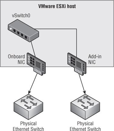
Figure 5.4 graphically summarizes these recommendations.
Figure 5.4 Use multiple connections from separate NICs in your ESXi hosts to separate switches for maximum redundancy.
Now, let's dive a bit deeper into protecting the specific traffic types in a vSphere environment. We'll start with management traffic.
Management Traffic
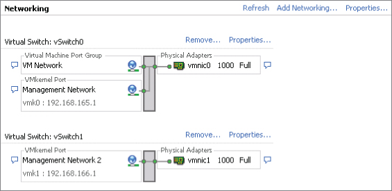
You have two options for planning for the redundancy of your management traffic. You can have either two management network ports on two separate vSwitches or one management network port with redundant NICs on the same vSwitch. Let's start with an example of the first option, as shown in Figure 5.5.
The first management network port is named Management Network. It has an IP address of 192.168.165.1 configured on vSwitch0, which uses vmnic0. The second management network port is named Management Network 2 and has an IP of 192.168.166.1 on vSwitch1 using vmnic1. By providing two management points into your ESXi host, you mitigate the risk of an SPoF for the management network. (Did you notice that the VM Network in Figure 5.5 has an SPoF? You should have!)
A certain amount of additional overhead is required in this sort of configuration. You need to apply some configuration changes to your cluster to accommodate such changes. These changes are as follows:
Figure 5.5 This ESXi host uses two management ports for redundancy.
das.isolationaddress[0] 192.168.165.254
das.isolationaddress[1] 192.168.166.254
das.failuredetectiontime 30000
Now, let's look at the second option to provide redundancy for your management network, illustrated in Figure 5.6.
Figure 5.6 This ESXi host has one management port but uses two NICs for redundancy.
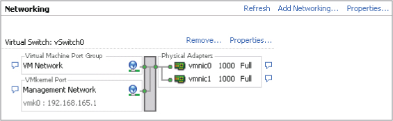
Here you use only one vSwitch and only one management port. This makes the configuration slightly easier and less complex. You don't need an additional IP address for the management ports, and you don't have to configure the additional settings required in the first option. You use two NICs that are set in an active-passive configuration. Each physical uplink (vmnic0 and vmnic1 in Figure 5.6) should be connected to a separate physical switch so that if one goes down, the other will continue to provide management connectivity for the ESXi host.
In vSphere 4.x environments, you should also set das.failuredetectiontime to 30000. Doing so prevents the occurrence of a false positive, which can cause you to end up with the VM being powered off (if you've set the configuration this way on your cluster settings) and not powered back up because the host no longer detects that it's isolated. For vSphere 5.x environments, see our earlier explanation of how this setting changed in vSphere 5.0 and vSphere 5.1.
Of these two options, what is the preferred configuration: two management ports or one (redundant management ports or redundant NICs)? That depends on a number of factors:
- How many NICs per host? If you're limited in the number of NICs available to you, then you probably can't dedicate two NICs to a management port.
- Can you make better use of the configuration by adding functions to the vSwitch (vMotion, for example)?
- Does your security policy allow for the mixture of management VLANs and other purposes (vMotion, IP storage, and VM traffic)? If not, then you'll need to use dedicated NICs.
In the end, it's a question of choices that depend on your environment.
Virtual Machine Traffic
Each ESXi host can run a multitude of VMs—the exact number always depends on the consolidation ratio you want to achieve and the capabilities of your infrastructure. A good portion of these VMs will need network connectivity outside the host onto your corporate network. So, when you're designing this portion of your infrastructure, you shouldn't be dependent on a single NIC or the connection to a single physical switch (advice we shared with you earlier, but it bears repeating). You'll need to plan for the redundancy of the VM traffic.
In the physical world, systems administrators would generally team the physical NICs either for load-balancing or for redundancy: basically, two network cables run into the server. You can do it that way in the virtual world, as shown in Figure 5.7.
Figure 5.7 Configuring NIC teaming at the guest OS level often isn't the best way to provide redundancy.
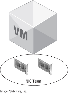
Although certain applications or guest OS configurations might require multiple NICs and teaming, it's generally not the best way to provide redundancy. Fortunately, providing redundancy for the VM traffic is remarkably easy—just provide redundant uplinks out of the vSwitch or dvSwitch hosting the VMs, and you're done. Yes, it really is that easy—most of the time.
Because a vSwitch/dvSwitch doesn't forward packets it has received back out again, it doesn't create bridging loops and therefore doesn't need to participate in STP. This also means you can have multiple active uplinks out of a vSwitch/dvSwitch that—using the default setting “Route based on the originating virtual port ID”—don't require any additional configuration on the upstream physical switches.
For the vast majority of workloads, this configuration is sufficient. Each time a VM is powered on, it's assigned to an uplink and continues to use that uplink until it's power-cycled or until the uplink fails and network traffic is passed to one of the other active uplinks in the virtual switch (or the port group).
Although this configuration is simple and provides adequate redundancy, it's not without its limitations. This setup doesn't provide efficient load balancing over all the uplinks in the virtual switch, and the traffic across the uplinks can become unbalanced in certain cases. In cases like that, or in cases where a VM's traffic patterns are predominantly many-to-one/one-to-many, then it might be beneficial to use link aggregation (“Route based on IP hash” is how link aggregation is denoted in the vSphere UI).
We discussed link aggregation extensively earlier (see the section “Link Aggregation”), so you know already that link aggregation isn't without its limitations. Notably, the traffic patterns need to be one-to-many/many-to-one; one-to-one traffic patterns won't benefit from link aggregation. Additionally, link aggregation requires support from the upstream physical switches, introduces additional complexity, and requires support for MLAG to avoid an SPoF.
If you're using a dvSwitch, you also have one other option: load-based teaming. With load-based teaming, no upstream switch configuration is required, and the dvSwitch will periodically evaluate physical NIC load to see if VM traffic needs to be rebalanced across the uplinks. It's a great feature and blends the best of both worlds. Unfortunately, it's only available with a dvSwitch, which requires Enterprise Plus licensing.
So which approach is best? Generally, we recommend keeping it as simple as possible. Unless the functional requirements drive the use of link aggregation, the default vSwitch/dvSwitch settings are generally acceptable for most installations.
IP Storage (NFS/iSCSI)
Earlier in this chapter, we discussed the differences between NFS and iSCSI as it pertains to the impact on your network designs, and we explained how iSCSI's use of MPIO allows iSCSI to use network architectures that wouldn't benefit NFS at all. In this section, we want to focus specifically on the mechanics of how you go about providing availability (in the form of redundant connections) for both iSCSI and NFS.
For iSCSI, we outlined the process earlier. Let's repeat it here for completeness:
Note that there are no underlying dependencies on physical switch support for link aggregation or anything like that. All you need is IP connectivity across multiple physical connections; the block storage stack in vSphere handles the rest.
For NFS, though, the situation is a bit more complex. With NFS, the architecture for building redundant connections depends wholly on the network—and thus depends wholly on mechanisms like link aggregation. Let's look at two configurations for NFS: one with link aggregation, and one without.
NFS with Physical Switches That Support Link Aggregation
Suppose your goal is to have your ESXi host access more than one storage controller from different physical uplinks. In this case, you have to set up multiple IP addresses in the storage controller and configure link aggregation on your ESXi host (and upstream switch). Configuring link aggregation on the storage array is optional but most likely beneficial. Figure 5.8 illustrates an example of such a setup.
Figure 5.8 This configuration uses link aggregation for both the ESXi host and the storage array.
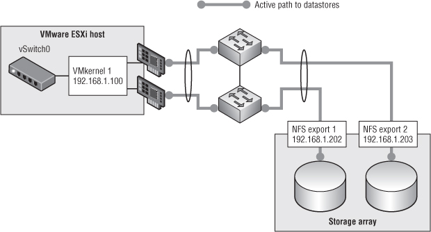
In this example, VMkernel 1 resides on a vSwitch that has been configured to use link aggregation. As a result, depending on the IP hash (recall that vSphere only uses a hash of source and destination IP to determine which link to use), traffic from VMkernel 1 could travel out either of the two uplinks.
If you used only a single target IP address hosting a single NFS export, you'd never use more than one of the two links. (If you don't understand why this is, go back and read the “Link Aggregation” section earlier in this chapter.) So, you need multiple target IP addresses. And because vSphere only associates an NFS datastore with a single IP address, you'll need multiple datastores. In Figure 5.8, you can see that the storage controller has two different IP addresses assigned to its interfaces—and has two different datastores that the ESXi host is accessing. Using link aggregation, each datastore is accessed on its own link.
There are a couple of key takeaways from this example:
- You'll need multiple target IP addresses on the storage system.
- Each NFS datastore will still only be associated with a single IP address (or DNS name); thus, each NFS datastore will be limited to a single link's worth of bandwidth.
- Although the aggregate bandwidth for all datastores increases (assuming the IP hashes spread the traffic evenly across the links), the individual bandwidth for a given NFS datastore won't increase (other than an increase due to potentially less contention on the network).
- If your switches don't support MLAG, you've introduced some SPoFs into your design—and that's not good. MLAG support is a must.
The nice thing about this approach is that it requires only a single VMkernel interface, and there aren't any strict requirements about the IP addresses that must be used. When the physical switches don't support link aggregation (or don't support MLAG), then the configuration looks quite different.
NFS with Physical Switches That Don't Support Link Aggregation
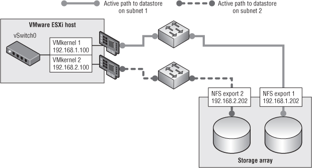
Now suppose the goal is the same, but the situation is more complicated than in the previous example. The storage controller still requires multiple IP addresses (and each NFS datastore on its own address), but they have to be on separate subnets. In addition, multiple VMkernel ports—also on separate subnets—are required. Figure 5.9 gives an example of such a configuration.
Why the need for multiple VMkernel interfaces, and why do they have to be on separate subnets? It's actually a simple IP routing issue—the VMkernel IP routing table can only select a single interface to use for any given IP subnet, so having multiple VMkernel interfaces on the same subnet means only one of the interfaces will be used. Using separate subnets introduces separate routes, one for each interface, and the VMkernel can then use all the interfaces. You only need to make sure you have an NFS datastore on the same subnet for each VMkernel interface.
Like link aggregation, though, this doesn't increase the per-datastore bandwidth, only the aggregate NFS bandwidth to all datastores. As we described in the “Link Aggregation” section, if you need more bandwidth to a single NFS datastore than can be provided by a 1Gb Ethernet link, your only option is 10Gb Ethernet.
Keep in mind that iSCSI and NFS implementations (on the storage target side) vary from vendor to vendor. Your vendor can provide the best practices for your specific environment.
Figure 5.9 Without link aggregation, NFS redundancy requires multiple datastores and multiple VMkernel interfaces.
vMotion
Why should you have redundancy for your vMotion interface? You may think this isn't an essential part of your enterprise. Well, you're wrong. Without a working vMotion interface, you can't balance your cluster properly, you can't evacuate your host if you need to perform maintenance, and more. You definitely need redundancy for your vMotion interface.
Does this mean you must have two dedicated NICs for this purpose? Probably not. You can use one of the NICs from your management network or VM network to provide redundancy in the case of failover. Usually the degradation in performance is acceptable for the short time until you restore the primary uplink used for vMotion. If you do feel you need multiple NICs for vMotion, we'll discuss options for that in the “Performance” section later in this chapter.
vSphere FT
vSphere FT is a relatively new feature that was made available in vSphere 4.0. In order for FT to work, you need a dedicated uplink that replicates the state of the VM from one host to another. You can't afford to have that uplink fail—if that happens, your VM will no longer be protected; and in the case of host failure, the secondary VM won't be available. Therefore, in the case of FT, you should have two dedicated uplinks going to separate physical switches to ensure that FT traffic doesn't get interrupted.
Although the current requirements for FT indicate that a 1Gb Ethernet link is sufficient, future enhancements to FT might require a 10Gb Ethernet link, so be sure you plan accordingly.
That's it for the first design principle of availability. The next design principle we'll discuss in the context of network design is manageability.
Manageability
From a network design perspective, we can think of two major areas for ensuring that the network is as manageable as possible. Both of these areas fall into the operational facet of vSphere design:
- Interoperability with existing network equipment and staff
- Naming and IP conventions
Let's look at interoperability first.
Interoperability with Existing Equipment and Staff
It's highly likely that the vSphere environment you're designing will be added to an existing network—one that has established standards for equipment, processes, procedures, and configurations. How interoperable is the design you're proposing with that existing network? Here are some things to think about:
- Using VMware's vSwitch or dvSwitch means the existing network group loses control over the last mile of the network (the access layer). Is this an acceptable shift of responsibility? What additional impacts will this change in ownership have on operational processes such as troubleshooting and provisioning?
- If the network group wants to retain control over the access layer, then perhaps something like Cisco's Nexus 1000V might be the right solution. The network team continues to manage it in much the same way they manage the rest of the network, and the 1000V creates a nice provider/consumer relationship between the network group and the VMware group.
- Will the network design integrate with existing network management solutions?
- Certain configurations—like using IP hashing on a VMware vSwitch or dvSwitch—require matching upstream configurations. The same goes for VLAN trunking and private VLANs. How will this impact the networking team's existing processes and procedures? Are the necessary standards and protocols supported for this design to function as expected?
These are just a few of the questions you'll want to be sure you have answers for when you examine your network design for manageability.
The second area of manageability centers on naming conventions and IP address assignments.
Naming and IP Conventions
It would be great if we could give any names we wanted to network components. After all, we name our children the way we want, give our pets names, and perhaps name a boat. But a network isn't the same as a family. Naming your VLANs Tom, Dick, and Harry may be amusing, but it isn't the way to do things in the enterprise.
For maximum manageability and operational efficiency, you should label your network components properly. They should be clearly identifiable even for those who don't manage the environment on a day-to-day basis. Here are a few examples:
- iSCSI_VLAN_765
- VM_VLAN_55
- 755_NFS
- 123_vMOTION
- Mgmt_1
Choose names that that can be recognized easily and associated with the appropriate VLAN.
In addition, be sure to create IP addresses in a consistent manner across all of your hosts. Table 5.1 shows an example of how not to do it.
Table 5.1 How not to assign IP addresses
| IP Address | |
| Management | 192.168.1.4 |
| NFS | 192.168.6.54 |
| vMotion | 192.168.4.20 |
| iSCSI | 192.168.20.222 |
This list has no standardization. When the environment grows, you won't be able to manage anything.
How about the example in Table 5.2?
Table 5.2 Standardized IP addresses
| Host 1 | Host 2 | |
| Management | 192.168.1.1 | 192.168.1.2 |
| NFS | 192.168.6.1 | 192.168.6.2 |
| vMotion | 192.168.4.1 | 192.168.4.2 |
| iSCSI | 192.168.20.1 | 192.168.20.2 |
We hope you can see the difference and how much easier it is when you keep things nice and tidy. Although it's not always possible to maintain a perfect numbering strategy, it's worth the effort to keep things as organized and consistent as possible.
Network Discovery Protocols
Another area that can prove beneficial with regard to manageability is the use of network-discovery protocols. vSphere supports two network discovery protocols: Cisco Discovery Protocol (CDP) and Link-Layer Discovery Protocol (LLDP). LLDP support was added vSphere 5.0; CDP support has been around for a while. As the name implies, CDP is specific to Cisco environments, although a number of other vendors (besides VMware) also support it. LLDP is a standards-based protocol supported by a number of different vendors.
Both of these discovery protocols allow devices that support them to exchange information across the network, making it easier to determine which ports are connected where and what devices are neighbors to other devices. Unless functional requirements dictate otherwise, we recommend enabling CDP (for predominantly Cisco-based environments) or LLDP (for non-Cisco or heterogeneous environments) on all your ESXi hosts. The minimal added work to do so (a simple GUI change or CLI command) is far outweighed by the additional information that is made available, and you'll be thankful for it when you're trying to troubleshoot a difficult network problem.
Moving on from manageability, it's time to look at the third design principle: performance. The performance of the network design is critical—without a well-performing network design, the entire vSphere environment will suffer, and the whole project might fail. The next section addresses how to design your network for performance.
Performance
What speed should your NICs be? The question should more accurately be, to what ports should your NICs be connected? Ideally, your NICs should be as fast as possible for everything, but that isn't practical. You could have a 10Gb Ethernet NIC for your management network, another for redundancy, two (or four) for IP storage, more for your VMs, and others for vMotion, but that would probably be extreme overkill.
Why should you care? Because each port has a cost. Here's an example. Suppose your server racks are equipped with a patch panel that goes to your corporate Tier-1 switches, and in addition an older Tier-2 10/100 Mb managed switch is used for all the remote control cards and backup ports for each server. The NICs connected to Tier-1 ports are more expensive than Tier-2. In most cases, a 10/100 Mb port is more than sufficient for remote-control cards, management ports, and backup NICs in a team that is mostly dormant. Your regular production traffic will go over the Tier-1 ports, and in the case of an outage on the primary NIC/port it will fail over to the Tier-2 port.
But what do you actually need? Let's look at the following components:
- Management network
- vMotion
- IP storage
- VM networking
Management Network
What level of traffic goes through your management port? If it's a dedicated management port used only for ESXi management, then not that much traffic goes through. In theory, a 10 Mb port would be more than enough, but finding such a port today is relatively impossible. You'll probably go for a 100 Mbps port, although even those can be scarce in some datacenters. A 1Gb Ethernet port is more than sufficient.
If you do decide to use a 100 Mb NIC, note that it's possible to saturate the throughput of that NIC. There are several ways to do that; the most common is to import a VM into your environment. The process when you're importing or converting a VM uses the bandwidth on the management network.
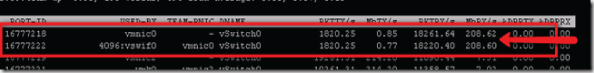
Figure 5.10 shows an example of an ESXi host running without any unusual load on vmnic0 (the management port).
When you begin an import process on a VM through the Enterprise Converter or the VMware stand-alone converter, all import traffic goes through the management port. As you can see in Figure 5.11, the traffic on that port can easily hit 200 Mbps, in which case a 100 Mbps port won't be sufficient.
Figure 5.10 esxtop is showing a normal network load on an ESXi host's management port.
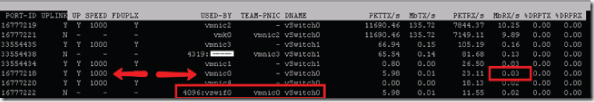
Figure 5.11 When converting a VM, esxtop shows heavy usage of the management port.
If you're planning to import a number of VMs into your environment or you plan to perform a large number of physical to virtual (P2V) conversions, you should definitely allocate a 1Gb Ethernet port for the management network.
vMotion
How fast do you want your host evacuated? How fast do you want your migrations to work? These are the questions that will drive how you provision your vMotion network.
Let's consider the following scenario. One of the hosts in your cluster just reported that a power supply failed. If you planned correctly, you have two power supplies in your host, so the server can run with only one power supply for a while; but server redundancy is now degraded, and you don't want to leave your server vulnerable. You should evacuate the host as soon as possible. So, you start to vMotion off your VMs (you have 60 on the host). Running on a 1 Gb NIC, you can perform four simultaneous migrations. Each migration takes 1 minute; that means you can vacate the host in 15 minutes, which is more than acceptable in our book. But using a 100 Mb NIC, that number will be more like 150 minutes, which isn't so acceptable. (As we noted earlier, it's becoming increasingly difficult to find ports that only run at 100 Mb in enterprise datacenters, so this isn't likely to be an issue. Further, vMotion requires 1 Gb NICs.)
You want the migration to go as quickly as possible. So, you could go for 10Gb Ethernet, but you should take into account the following. Starting with 4.1, the number of concurrent vMotions was increased to eight from four, and the speed cap on a 10Gb Ethernet link for vMotion was raised to 8 Gbps. If you aren't careful, you may saturate the 10 Gb NIC with only vMotion. This isn't a good thing. You'll generally be using the NIC for other purposes as well (VM traffic or IP storage). If this is the case, you'll have to incorporate some kind of network QoS on the NIC to ensure that the vMotion interfaces don't saturate the interface.
Also recall from our earlier discussion of 10Gb Ethernet that a 10 Gb NIC that has been subdivided into separate logical NICs will be treated as a 1 Gb NIC for the purposes of calculating simultaneous vMotion operations (so the limit will drop back to four).
In addition, newer versions of vSphere introduced support for multi-NIC vMotion, which allows vSphere to use multiple NICs simultaneously to further speed up VM migrations. If you want faster migrations but can't afford (or don't want) to migrate to 10Gb Ethernet, this might be an option to incorporate into your design.
IP Storage
IP storage has grown from being a second-level storage platform to being a more mainstream enterprise-grade storage platform. The I/O performance you can achieve from a 10 Gb NIC is no worse than the speeds you can achieve with Fibre Channel (FC) storage. But the number of 1 Gb NICs needed to achieve performance equal to FC is considerably higher, and the configuration is much more complex to achieve the same results. Further, as we described earlier (in the “Link Aggregation” and “Availability” sections), no matter how many NICs you throw at NFS, it will only use one link per datastore.
Therefore, the default choice for IP storage should be 10 Gb NICs. This is especially true for compute nodes with limited slots, like blades. Add in NIOC to maximize performance and options for fan-in growth in your datacenter. This, of course, assumes you have the infrastructure in place—if not, then you should plan to make this your standard for the future.
One final consideration regarding IP-based storage is in regard to the use of DNS for NFS mount points. If your design uses a scale-out NFS storage platform (there are a number of examples on the market, such as EMC Isilon and NetApp in Cluster mode), then using DNS round robin—a single DNS name backed by multiple IP addresses—for your NFS mount might improve performance by spreading the workload across multiple connections. Each ESXi host will still use only a single connection, but aggregate traffic from multiple hosts will potentially benefit.
VM Networking
Each VM needs a certain amount of bandwidth, and there is no one-size-fits-all solution. You'll have do your homework and measure (or estimate) the amount of network traffic each VM will use. If you're converting a physical server, then collecting the data beforehand should be part of your policy before you migrate the server.
We won't go into the details of how this can/should be performed on Windows/Linux servers; we'll leave that to you and your corporate policies and procedures. But when you have this data, you can estimate how many VMs can reside on each NIC. You then size your host accordingly, taking into account the network information. It may be that one 1 Gb NIC will suffice for your environment, or it may be that two 10 Gb NICs won't suffice.
The bottom line, for all the different vSphere traffic types, is to plan according to your sizing needs. ESXi can accommodate your needs regardless of the speed of your NIC.
With availability, manageability, and performance out of the way, let's now discuss recoverability.
Recoverability
To ensure that your network design is recoverable, you'll want to do the following things:
The last design principle we'll discuss is security. Although it's listed last, it's certainly not least, as you'll see in the next section.
Security
Security shouldn't be an afterthought—you should take the time to look at the components of your design from the point of view of security. Always consult the VMware site for updated recommendations on securing your vSphere infrastructure. VMware currently offers a vSphere 4.0 Security Hardening Guide:
www.vmware.com/files/pdf/techpaper/VMware_vSphere_HardeningGuide_May10_EN.pdf
There is a Security Hardening Guide for vSphere 4.1 as well:
www.vmware.com/resources/techresources/10198
VMware also has a Hardening Guide for vSphere 5.0:
http://communities.vmware.com/docs/DOC-19605
At the time of this writing, a Security Hardening Guide for vSphere 5.1 had not been released.
With regard to a vSphere network design, the security focus is primarily on the various network traffic types. We'll be discussing the following kinds of traffic in this section:
- Management network traffic
- VM traffic
- IP storage traffic
- vMotion and FT traffic
Management Network
Do your domain controllers and mail servers sit on the same subnet as your desktop computers? We hope not! They shouldn't, because your corporate servers should be separate from your end users. This arrangement provides the option to protect your server farm from outside attacks. We don't mean attacks from outside your network but rather from inside your network due to a computer being compromised and acting as an attack point into the server farm. Some enterprise organizations have their server farms behind a firewall with IPS and IDS systems protecting their critical servers.
Your vSphere environment should definitely be treated as a critical server. The risk of the environment being exploited if it's compromised is potentially disastrous. If someone takes control of your vCenter Server, they gain control of every VM in your environment. If they take control of one host, they have control of every VM running on that host.
Therefore, your management network should be separate from the rest of your virtual environment. And it isn't the only element that should be separated. vMotion, IP storage, and FT should be separate as well; we'll get to those later in this section.
How do you separate your management network? Dedicate a network segment specifically for this purpose. Some enterprises have dedicated subnets for out-of-band (OOB) management devices such as Integrated Lights Out (iLO) ports. Some define the management network on an ESXi host as an OOB port, because the management network is there only to provide management to either the vSphere Client or the vCenter Server on that host. You can also provide a new dedicated subnet, depending on your corporate policy.
With this segregation, you can provide the correct network-access lists on this segment to secure your environment even further.
VM Traffic
When you start, you'll be hosting a few VMs. Then the number will grow. In the not-too-distant future, you'll be providing virtualization services for a great number of VMs. You don't want to have all those VMs (production servers, desktops, lab machines, test and development machines, and so on) on the same subnet. You segregate traffic on the physical network exactly the same way you should separate it on a virtual network: production servers on this subnet, desktops here, and so on. VMware makes this extremely easy with VLAN tagging on VM port groups. All the VMs may be running on the same two physical uplinks, but they're on different VLANs with different IP addresses.
You must make sure that all the VLANs are trunked correctly to the appropriate ports on the physical switch and that the port groups are defined on all the hosts that are in the same cluster. Otherwise, the VMs will disconnect from the network if an uplink fails or they're migrated to another host.
You should work with your network team to define a solid policy that will work well in your environment. The option of assigning all VLANs up front to every port is very appealing because it would require a one-time configuration for each ESXi host. But in some environments, having all the VLANs open on the uplinks will cause problems. Multicast network traffic is a good example.
vMotion and FT Traffic
vMotion of a VM between hosts is a necessity for most enterprise environments, whether for planned maintenance or to balance machines with distributed resource scheduling (DRS). When you migrate the machine from one host to another, the VM disk isn't migrated over the network—only the VM's live running state (CPU execution, memory contents, and network). None of this traffic is encrypted, so someone could eavesdrop on the traffic and acquire the information flowing at that time, which could be a security risk.
If you're performing a Storage vMotion, which takes much longer, the powered-off VM is transferred over the network (unless your array supports vSphere APIs for Array Integration [VAAI]). This information can also be compromised.
In this case, the earlier solution of network segregation and a nonroutable VLAN will minimize the attack surface and provide a level of protection. This segregation should also be done with FT traffic.
IP Storage Network Traffic
When we say IP storage, we're talking about NFS or iSCSI. There are good use cases for both network protocols (as we've already discussed), but this traffic isn't encrypted, and it travels over the wire. Anything that travels over the wire can potentially be tapped with a packet sniffer—and may compromise your security.
How can you protect this traffic? We'll discuss three ways. They aren't either/or solutions but can be used together in the appropriate use cases:
- VLAN isolation and a nonroutable VLAN
- NFS export (/etc/export)
- iSCSI CHAP authentication
- VLAN Separation
- This approach is valid for both iSCSI and NFS (as well as all the other types of vSphere traffic). Your IP storage should be on a separate network segment. This helps by segregating IP storage from the rest of your network and thus limiting the attack surface to only that segment. An attacker must have an interface on that segment to eavesdrop on the traffic.
- To extend this concept, the VLAN should be nonroutable. This ensures that only interfaces on the same network can reach the VMkernel and IP storage interfaces.
- NFS Exports
- This approach applies only to NFS. When you create the NFS export on your storage, be it an enterprise-grade storage array or a Linux server providing NFS, you should always limit the hosts that are allowed access to NFS shares. Doing so limits who can access the filesystems where your VMs are stored.
- You do this using the exports file. The /etc/exports file specifies remote mount points for the NFS mount protocol per the NFS server specification. On some arrays, you use the GUI rather than configuring the file itself.
- Let's look at an example. If you want to define the export to folder /vol/nfs1 to all the hosts on the 192.168.0.0/24 segment (254 hosts), you configure the export as shown here:
192.168.0.0/255.255.255.0 (rw,no_root_squash)
192.168.0.45 (rw,no_root_squash)
- Rebuild and copy the files and filesystems being transferred on the network.
- Alter the contents of files by injecting fake iSCSI frames.
- Corrupt filesystems being accessed by initiators and exploiting software flaws.
Before we wrap up this chapter, we'd like to take all the information we've presented and pull it together with a few network-design scenarios.
Design Scenarios
Last but not least in this chapter, we'll provide some scenarios of ESXi host configuration with two, four, six, or eight NICs. In all the design scenarios, each host has the following:
- Management port
- VMkernel for IP storage
- VMkernel for vMotion
- VM port group 1
- FT port
We assume the use of multiple physical switches upstream to ensure that there is redundancy at the physical network layer as well.
Two NICs
This isn't a good idea. You can't provide proper performance, security, isolation, or redundancy with only two NICs. Can such a design be done? Yes. Do we recommend it? No. With that off our chest, let's start.
VM traffic goes through vmnic1; management, vMotion, IP storage, and FT are on vmnic0, as you can see in Figure 5.12.
Figure 5.12 This figure shows a sample configuration with two NICs.
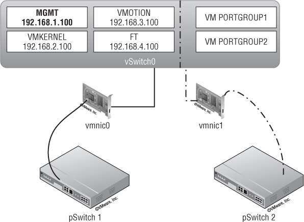
The only time two NICs would be acceptable is if you were using two 10Gb Ethernet NICs. In that case, the configuration would be as described previously: a single vSwitch with two uplinks, and traffic split across the uplinks by setting the NIC failover order on each port group.
Four NICs
In this case, traffic is split between two virtual switches, each with two uplinks. vSwitch0 handles management, IP storage, vMotion, and FT; vSwitch1 handles VM traffic. The port groups on vSwitch0 are configured to use a custom NIC failover order so that management and IP storage run on one of the uplinks and vMotion and FT run on the other uplink (with the ability for either group to fail over to the other uplink if necessary). Figure 5.13 illustrates this configuration.
Figure 5.13 This ESXi host has two vSwitches, each with two uplinks.
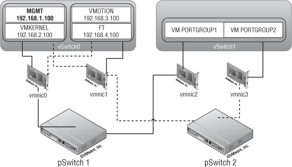
The solid lines represent the primary links for each component, and the dotted lines represent the backup links. Here you provide redundancy for the VM traffic and some sort of redundancy for console and other traffic. This isn't ideal because too many components are competing for the same resources on vSwitch0.
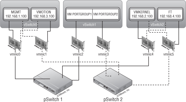
Six NICs
Here, VM traffic goes through vSwitch1 (vmnic2 and vmnic3, both active). vSwitch0 handles management traffic on vmnic0 (active; vmnic1 on standby) and vMotion on vmnic1 (active; vmnic0 on standby). On vSwitch2, IP storage goes through vmnic4 (active; vmnic5 on standby) and FT through vmnic5 (active; vmnic4 on standby). This is all illustrated in Figure 5.14.
You have redundancy for all components, but the FT and IP storage traffic have only one NIC each. Depending on the size of the environment, this might not provide enough throughput for either of the two functions.
Figure 5.14 A six-NIC configuration provides redundancy for all components.
Eight NICs
In this scenario, VM traffic goes through vSwitch1 (vmnic2 and vmnic3, both active). On vSwitch0, management traffic goes through vmnic0 (vmnic1 on standby) with vMotion on vmnic1 (vmnic0 on standby). vSwitch2 handles IP storage (vmnic4, vmnic5, and vmnic6 active with vmnic7 on standby) and FT (on vmnic7, with vmnic6 and vmnic5 on standby). Figure 5.15 shows this configuration.
Figure 5.15 A configuration with eight NICs provides both redundancy and scalability.
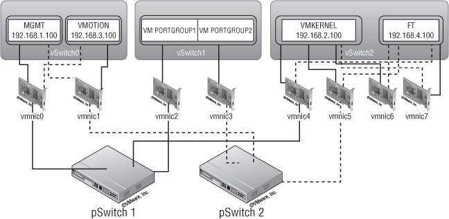
Here you have redundancy for all components, and IP storage traffic has reasonable throughput using three NICs (keep in mind that, depending on the type of IP storage, it might be difficult to get it to fully utilize all three NICs). FT is limited to one NIC, which will limit the number of FT VMs you can host.
We hope these design scenarios give you some ideas of the flexibility you have in creating your vSphere network design. Although many different factors and considerations will shape your network design, vSphere offers a range of solutions and features to help ensure that you're able to satisfy the functional requirements.
Looking to the Future
Naturally, we must focus the majority of our discussion on what is available today for you to use in your vSphere design. However, it's also important to take a quick look at the near future and examine some standards and protocols that might affect how you do vSphere network designs:
These are just three potential areas that might affect your vSphere network designs in the near future. We encourage you to stay closely connected to developments in the networking industry so you're prepared for the impacts to your designs as these developments unfold.
Summary
Designing any part of your virtual infrastructure isn't easy. It's a lengthy and complicated process, with many parameters that have to be taken into account.
Plan for that rainy day when things go bad. You may receive a small token of appreciation if you save a few bucks, but we assure you that you won't receive flowers if your environment crashes because you don't have the proper redundancy measures in place. You must consider your network standard—1Gb or 10Gb Ethernet—and learn the best way to set up your network for your specific environment.
Now, we'll move on to another critical part of the infrastructure: storage.