

GDPS/XRC
In this chapter we discuss the capabilities and the prerequisites of the GDPS/XRC offering.
The GDPS/XRC offering extends the benefits of GDPS to installations that have a requirement for extended distance remote copy support. However, it is important to understand that GDPS/XRC is not simply GDPS/PPRC with a longer distance between the sites; there are additional differences which are discussed in this chapter.
This chapter describes the following capabilities of GDPS/XRC:
•Protecting your data
– Protecting the integrity of the secondary data (both disk and tape) in the event of a disaster or suspected disaster
– Management of the remote copy environment both through scripts and through a NetView panel interface
– Support for remote copy management and consistency of the secondary volumes for data that is not z/OS data, coordinated with management of the z/OS data
•Controlling the resources managed by GDPS during normal operations, planned changes, and following a disaster
– Management of the System Data Mover (SDM) LPARs (shutdown, IPL, and automated recovery)
– Support for switching your production data and systems to the recovery site
– User-customizable scripts that control how GDPS/XRC reacts to specified error situations and that can also be used for planned events
5.1 Introduction to GDPS/XRC
Extended Remote Copy (XRC), rebranded to IBM System Storage z/OS Global Mirror, is a combined hardware and software asynchronous remote copy solution. Consistency of the data is maintained through the Consistency Group function within the z/OS System Data Mover (SDM).
Because of the asynchronous nature of XRC, it is possible to have the secondary disk at greater distances than acceptable for PPRC. Channel extender technology can be used to place the secondary disks up to thousands of kilometers away. Because XRC is asynchronous, the impact it has on response times is minimal, and is independent of the distance between the primary and secondary volumes.
GDPS/XRC combines the benefits of GDPS with the extended distance capabilities of XRC. It includes automation to manage replication and automates the process of recovering the production environment with limited manual intervention, including invocation of CBU1, thus providing significant value in reducing the duration of the recovery window and requiring less operator interaction.
Whereas GDPS/PPRC is a high availability and disaster recovery solution for a single multisite sysplex, GDPS/XRC is specifically an automated disaster recovery solution. GDPS/XRC controls the remote mirroring and automates the recovery of production data and workloads in the recovery site. The systems running GDPS/XRC are typically in the recovery site, remote from the production systems, and are not members of the sysplex at the primary site. Additionally, unlike GDPS/PPRC, GDPS/XRC has no knowledge of what is happening in the production systems. The only resources GDPS/XRC is aware of are the replication resources and the hardware resources in the recovery site. Following a disaster, the production systems are restored by GDPS/XRC at the recovery site.
Because XRC is an asynchronous remote copy technology, it is not possible to have zero data loss when using XRC. Hence, the Recovery Point Objective when using XRC must be more than zero, meaning that some minimal data loss is acceptable. In a typical XRC configuration, an RPO of one minute should be achievable. With sufficient bandwidth, clients with large configurations are able to maintain an RPO of 1 to 5 seconds.
The Recovery Time Objective for GDPS/XRC is not dissimilar to that achievable with GDPS/PPRC, typically between one and two hours. This is because GDPS/XRC automates the entire process of recovering the XRC mirror, activating temporary backup capacity, and restarting the production systems.
5.1.1 Protecting data integrity
With PPRC, you need to apply some automation (for example, the GDPS/PPRC Freeze function) on top of the standard PPRC functions to guarantee the integrity of the secondary disk across multiple subsystems. However, in GDPS/XRC, the design of XRC guarantees the integrity of the secondary disk data. The role of GDPS, from a remote copy perspective, is to manage the remote copy configuration and to drive the recovery process.
Protecting data on disk
The following systems support time stamping of I/Os when the target volume has been defined as a primary XRC volume:
•Any supported release of z/OS.
•System z for Linux drivers support timestamping of writes and also contain changes to support device blocking.
•z/VM and its guests.
CKD volumes used by any number of these systems, which we will refer to as production systems, can be managed by GDPS/XRC. Additionally, any number of sessions or Master sessions can be managed by GDPS/XRC. The volumes managed by an SDM or multiple SDMs that are coupled under the same Master session can be managed to a single point of consistency. For more information, see “XRC data consistency” on page 27.
If you have two z/OS sysplexes running your production workload, you can choose to XRC the entire data for those sysplexes under a single Master session (that is, as a single consistency group). In this case, however, if there is an incident that forces you to recover one of these sysplexes, you will need to recover both; you cannot recover one in the recovery site and leave the other running in the application site. If you need to recover them individually, then you would use two separate Master sessions, one for the data of each sysplex. A single instance of GDPS/XRC can manage these two different sessions.
It is also possible to use XRC to remote copy volumes being used by System z operating systems that do not time stamp their I/Os (for example, z/VSE). However, in this case it is not possible to provide consistency across multiple LSSs. For more information, see “Understanding the Importance of Timestamped Writes” in the latest revision of z/OS DFSMS Advanced Copy Services, SC35-0428.
z/OS is the only operating system that supports running the System Data Mover function that performs the XRC replication. Therefore, in a GDPS/XRC configuration, you need a minimum of two z/OS systems: one to provide the SDM function, and one dedicated GDPS Controlling system. More than one SDM system might be required, depending on the amount of data to be replicated. SDM system(s) and the GDPS Controlling system must be clustered into a Base or Parallel Sysplex to facilitate GDPS communication among the systems.
5.1.2 Protecting tape data
Although most of your critical data will be resident on disk, it is possible that some of the data you require following a disaster will reside on tape. Just as you mirror your disk-resident data to protect it, equally you can mirror your tape-resident data. GDPS/XRC provides support for a single integrated recovery process when using a IBM TotalStorage 3494-based Virtual Tape Subsystem in a Peer-to-Peer configuration.
5.2 GDPS/XRC configuration
A GDPS/XRC configuration consists of one or more production systems and/or sysplexes updating the primary volumes in the production site, one or more SDM systems in the recovery site, and one GDPS Controlling system (K-sys), also in the recovery site. The SDM system(s) and the Controlling system must be in the same sysplex. There is no requirement for the production system to be in a sysplex; however, all the systems updating the primary volumes must be connected to the same Sysplex Timers or the same Server Time Protocol (STP) network. Figure 5-1 shows a simplified illustration of the physical topology of a GDPS/XRC implementation.

Figure 5-1 GDPS/XRC topology
As with all GDPS products, the GDPS/XRC controlling system is responsible for all remote copy management functions and for managing recovery following a disaster, so its availability is critical. Unlike a GDPS/PPRC configuration, however, there is no requirement to isolate the controlling system disks from the other systems in the GDPS sysplex (the SDM systems). The SDM systems and production systems can share infrastructure disks such as system residency volumes, the master catalog, the IBM RACF® database, and so on.
All critical data resides on storage subsystems in Site1 (the primary copy of data) and is mirrored to the storage subsystems in Site2 (the secondary copy of data) through XRC asynchronous remote copy. The systems in Site2 must have channel connectivity to the primary disk. Most clients use channel extension technology to provide this connectivity; there is no requirement for dark fiber between the sites.
In a more complex configuration, where you have more primary volumes, you might exploit the Coupled SDM and Multi-SDM support, both of which allow you to have a single point of consistency across multiple SDMs. GDPS/XRC supports both Coupled SDM and Multi-SDM.
In an even more complex configuration, GDPS/XRC can manage multiple master sessions, so you potentially can have two separate production sites, both using XRC to remote copy to a single recovery site, and have a single GDPS/XRC manage that recovery site and all associated XRC sessions.
5.2.1 GDPS/XRC in a three-site configuration
GDPS/XRC can be combined with GDPS/PPRC (or GDPS/PPRC HM) in a three-site configuration, where GDPS/PPRC (or GDPS/PPRC HM) is used across two sites within metropolitan distances (or even within a single site) to provide continuous availability through Parallel Sysplex exploitation and GDPS HyperSwap, and GDPS/XRC is used to provide disaster recovery in a remote site.
We call this combination GDPS/Metro z/OS Global Mirror (GDPS/MzGM). In this configuration GDPS/PPRC and GDPS/XRC provide some additional automation capabilities.
After you understand the base capabilities described in 2.4.4, “Combining disk remote copy technologies for CA and DR” on page 34, refer to Chapter 9, “Combining Local/Metro continuous availability with out-of-region disaster recovery” on page 237 for a more detailed discussion of GDPS/MzGM.
5.3 GDPS/XRC management of distributed systems and data
GDPS/XRC provides the Distributed Cluster Management (DCM) capability for managing global clusters using Veritas Cluster Server (VCS) with the Global Cluster Option (GCO). When the DCM capability is used, GDPS/XRC does not manage remote copy or consistency for the distributed system data (this is managed by VCS). Therefore, it is not possible to have a common consistency point between the System z CKD data and the distributed data. However, for environments where a common consistency point is not a requirement, DCM together with VCS does provide key availability and recovery capabilities which might be of interest. DCM is discussed in further detail in 8.3.2, “DCM support for VCS” on page 215.
5.4 Managing the GDPS environment
GDPS/XRC only monitors the systems that comprise the GDPS sysplex - the SDM systems and the Controlling system. This is shown in Figure 5-2. If all systems in the production site were to go down, GDPS/XRC has no automatic knowledge of this event. However, GDPS/XRC is able to monitor the recovery site server hardware, and it provides capabilities to manage these resources to automate restart of production in the recovery site.

Figure 5-2 GDPS/XRC span of control
5.4.1 NetView interface
The NetView interface for GDPS actually consists of two parts. The first, and potentially the most important, is NetView’s Status Display Facility (SDF). Any time there is a configuration change, or something in GDPS that requires manual intervention, GDPS will send an alert to SDF. SDF provides a dynamically-updated color-coded panel that provides the status of the systems and highlights any problems in the remote copy configuration. At all times, the operators should have an SDF panel within view so they will immediately become aware of anything requiring intervention or action.
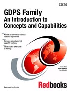
The other aspect of the NetView interface consists of the panels provided by GDPS to help you manage and inspect the environment. The main GDPS panel is shown in Figure 5-3.
Figure 5-3 Main GDPS/XRC panel
From this panel, you can:
•Query and control the disk and tape remote copy configuration
•Initiate standard actions provided by GDPS against LPARs managed by GDPS (such as IPL, LPAR Deactivate, and so on)
•Initiate GDPS scripts that you create
•Manage Coupling Facilities and Couple Data Sets relating to the SDM sysplex
•Manage the GDPS Health Checks
•Change or refresh the remote copy configuration definitions
•Run GDPS monitors
Remote copy panels
Although z/OS Global Mirror (XRC) provides a powerful replication capability, the operator interface to it is not particularly user-friendly. To make it easier for operators to check and manage the remote copy environment, use the Disk Remote Copy panels provided by GDPS.
For GDPS to manage the remote copy environment, you must first define the configuration (primary and secondary device numbers, FlashCopy devices, and information about the sessions and SDMs) to GDPS in a file called the GEOXPARM file.
After the configuration is known to GDPS, you can use the panels to check that the current configuration matches the desired one. You can start, stop, suspend, and resynch mirroring at the volume or LSS level, you can initiate a FlashCopy of the secondary volumes, perform coupled SDM operations, move SDMs to different LPARs, and so on. These actions can be carried out at the device or LSS level, or both, as appropriate. Figure 5-4 on page 133 shows the mirroring panel for GDPS/XRC. In this example you see that GDPS is managing four SDM sessions. One of these, SDM04, is a stand-alone session. The remainder are coupled under a single Master named MSDM.

Figure 5-4 GDPS/XRC DASD Mirroring Session Status panel - main view
If you are familiar with the TSO interface to XRC, you will appreciate how much more user friendly the panel is.
Remember that these panels provided by GDPS are not intended to be a remote copy monitoring tool. Because of the overhead involved in gathering the information from all devices across all SDMs to populate the NetView panels, GDPS only gathers this information on a timed basis, or on demand following an operator instruction. The normal interface for finding out about remote copy problems is through SDF.
Standard Actions
We previously discussed how the overwhelming majority of System z outages are planned outages. Even though GDPS/XRC only manages the SDM systems in the recovery site, it is still important that those systems are available and are correctly managed. GDPS provides facilities to help manage any outages affecting these systems. There are two reasons to use the GDPS facilities:
•They are well-tested and based on IBM recommended procedures.
•Using the GDPS interface lets GDPS know that the changes it is seeing (CDSs being deallocated or systems going out of the sysplex, for example) are planned changes, and therefore it is not to react to these events.
There are two types of resource-altering actions you can initiate from the panels: Standard Actions and Planned Actions. Standard Actions are really single-step and are intended to perform an action on just one resource. Examples are performing a graceful shutdown of one of the systems in the GDPS sysplex, IPLing a system, maintaining the IPL address and the Loadparms that can be used for each system, selecting the IPL address and Loadparm to be used the next time a system is IPLed, and activating or deactivating or resetting an LPAR. For example, if you want to stop a system, change its IPL address and then IPL it again, those are three separate Standard Actions that you will initiate.
The GDPS/XRC Standard Actions panel is shown in Figure 5-5. It displays all the LPARs being managed by GDPS/XRC, and for each one, it shows the current status and various IPL information. It also shows (across the top) the actions that can be carried out on each system, including Stop, re-IPL (stop followed by IPL), Activate, and Deactivate. You will also see that there are some systems with status MANUAL. These are not systems in the GDPS sysplex. They are the “recovery systems,” which are the systems that GDPS can restart in the recovery site using recovered XRC disks or FlashCopy disks. Hence it is possible to perform hardware actions (activate/deactivate the partition, load, reset, and so on) against such foreign systems as well.

Figure 5-5 Standard Actions panel for GDPS/XRC
GDPS provides support for taking a stand-alone dump using the GDPS Standard Actions panel. The stand-alone dump can be used against any System z operating system defined to GDPS, either a GDPS system (SDM and Controlling systems) or foreign system (production recovery system), running native in an LPAR. Clients using GDPS facilities to perform HMC actions no longer need to use the HMC for taking stand-alone dumps.
5.4.2 GDPS scripts
Nearly all of the functions that can be initiated through the panels are also accessible from GDPS scripts. Additional facilities, not available on the panels, are also available using scripts. A script is a “program” or a workflow consisting of one or more GDPS functions. Scripts can be initiated manually through the GDPS panels (Planned Actions), and certain scripts can be initiated automatically by GDPS in response to an event (referred to as an Unplanned Action), or through a batch interface.
Scripts are written by you to automate the handling of certain situations, both planned changes and also error situations. This is an extremely important aspect of GDPS.
Scripts are powerful because they can access the full capability of GDPS. The ability to invoke all the GDPS functions through a script provides the following benefits:
•Speed
The script will execute the requested actions as quickly as possible. Unlike a human, it does not need to search for the latest procedures or the commands manual. Results of each command in the script are also analyzed and interpreted quickly. Result checking for such compound/complex actions by a human would require more in-depth skills in a variety of disciplines.
•Consistency
If you were to look into most computer rooms immediately following a system outage, what might you see? Mayhem! Operators frantically scrambling for the latest system programmer instructions. All the phones ringing. Every manager within reach asking when the service will be restored. And every systems programmer with access vying for control of the keyboards. All this results in errors, because humans naturally make mistakes when under pressure. But with automation, your well-tested procedures will execute in exactly the same way, time after time, regardless of how much you shout at them.
•Thoroughly tested procedures
Because scripts behave in a consistent manner, you can test your procedures over and over until you are sure they do everything that you want, in exactly the manner that you want. Also, because you need to code everything and cannot assume a level of knowledge (as you might with instructions intended for a human), you are forced to thoroughly think out every aspect of the action the script is intended to undertake. And because of the repeatability and ease of use of the scripts, they lend themselves more easily to frequent testing than manual procedures.
Planned Actions
Planned Actions are GDPS scripts that are initiated from the GDPS panels (option 6 on the main GDPS panel, as shown in Figure 5-3 on page 132). A Planned Action script might consist of a number of tasks. For example, you can have a script that will stop an LPAR, change its IPL address to the alternate SYSRES, and then re-IPL it, all from a single script.

Figure 5-6 GDPS/XRC Planned Action
A more complex example of a Planned Action is shown in Figure 5-6. In this example, a single action in GDPS results in a tertiary copy of the secondary disks being taken, followed by IPLing the “production” systems in LPARs in the recovery site. This allows you to test your recovery procedure in the recovery site while live production continues to run in the application site and live production data continues to be protected by XRC to maintain up-to-date disaster readiness.
Specifically, the following actions are carried out by GDPS in this script:
•Zero Suspend FlashCopy is initiated:
– This prevents the SDMs from writing new consistency groups to the secondary disks for a few seconds.
– A FlashCopy is taken of all XRC secondary devices and the XRC infrastructure devices (the devices housing the XRC state, control, and journal data sets).
– Zero Suspend FlashCopy completes and SDM processing resumes writing new consistency groups to the secondary disks.
•An XRC recover on the tertiary devices is performed.
•Temporary CBU capacity on CPCD is activated.
•Any test systems whose LPARs will be used for a recovery system in case of a disaster are deactivated.
•The CF LPARs and the LPARs that will house the recovered production systems are activated.
•The production recovery systems are IPLed.
As a result of a single action that you performed (initiating the Planned Action), you have stopped discretionary work in the recovery site, created a copy of your production data and systems, and increased capacity, all while live production continued to run and maintain disaster readiness.
The use of a scripting capability removes the reliance on paper procedures which are invariably apt to go out of date, and ensures that the process is carried out the same way every time, with no vital steps accidentally overlooked.
Region Switch
GDPS defines a process for performing a planned Site Switch (also referred to as a Region Switch) between the two sites that act as the application and recovery sites. This process can be used for a planned Region Switch, and to return home to the original application region after an unplanned recovery (failover) to the recovery region.
The GDPS/XRC product provides capabilities that will assist with and simplify various procedural aspects of a Region Switch or Return Home operation.2
It is most likely that you will perform regular, planned region switches if your two regions are symmetrically configured, although this is not strictly mandatory. A symmetrically configured environment provides the same capabilities and allows you to use nearly identical procedures, no matter which region hosts the production systems and which region is the recovery site (hosting the GDPS/XRC environment). A symmetric configuration where there is tertiary FlashCopy capacity available in both regions is referred to as a 2+2 configuration. A 1+1 configuration is also symmetrical but does not provide the benefits associated with tertiary FlashCopy capacity no matter which region is hosting production and which is the recovery region.
Typically you run production in Region A, and Region B is the recovery site where you are likely to also have tertiary disks (FlashCopy capacity). If you do not have FlashCopy capacity in Region A but do in Region B, this is what we call a 1+2 configuration which is not symmetrical. If you switch production to run in Region B, your recovery site in Region A is not equipped with tertiary disk and does not provide equivalent protection and ability to test, compared to running production in Region A and using Region B for recovery. Some of your operational procedures associated with GDPS will be different when running production in Region B versus when running in Region A.
The procedural steps for switching regions for a 1+1, 1+2, and for a 2+2 configuration will have similarities, but there will also be differences due to the differences in these configurations. The key difference is that the 2+2 configuration Region Switch will benefit from having the FlashCopy capacity in both sites, which will facilitate a faster switch with the least possible downtime to production systems when performing the switch.
At a high level, the sequence for moving production services from one region to the other includes these procedural steps:
1. Assume your production is running in Region-A and GDPS (Controlling system and SDM systems) is running in Region-B.
2. Quiesce the production systems in Region-A and wait for the last updates to drain to Region-B.
3. Start the GDPS environment in Region-A.
4. Reverse replication from Region-B to Region-A and stop the SDM systems in Region-B.
5. Reversing replication does not require any data to copy because the source and target disks have identical content.
6. Start production systems in Region-B using GDPS facilities.
This procedure results in having production running in Region-B, GDPS running in Region-A, and achieving continuous DR protection.
Return Home after an unplanned failover to the recovery region
You might have to recover your production operations in the recovery region as a result of a catastrophic failure in the original application region. After running production in the recovery region for some time, if you want to return operations back to the original application region when it has been restored, you can use a modified version of the region switch procedure. The key difference is that return home requires all data to be copied back to the original application region. After all data is copied back, then the operation to return is effectively a region switch as described in “Region Switch” on page 137.
Unplanned Actions
Unplanned Actions are GDPS scripts (also known as Takeover scripts), just like Planned Actions. However, they are used in a different way. Planned Actions are initiated from the GDPS panels. Unplanned Actions are initiated by GDPS in response to a failure event.
Remember that in a GDPS/XRC environment, GDPS only has knowledge about what is happening in the GDPS sysplex in the recovery site. GDPS does not monitor and therefore cannot detect failures in the application site. The script to recover XRC and restart production in the recovery site would be defined as a Planned Action. You could view this as a pre-planned, unplanned action.
In GDPS/XRC, Unplanned Actions are only used to react to failure of an SDM system or the GDPS Controlling system (remember that the GDPS code runs in every system, so if the Controlling system fails, GDPS in one of the SDM systems will detect that and react with an Unplanned Action script). The intent of such a script would be to re-IPL the failed system. Such scripts are not run automatically. GDPS will detect the failure and propose running the appropriate script. The operator would then have the choice of accepting to run the script in which case GDPS would initiate it, or to do nothing.
Batch scripts
Because the full range of GDPS functions is available to you, you can have scripts that will carry out normal operational processes for you. This is especially suited to processes that are run regularly, and have some interaction with the GDPS environment.
One of the challenges faced by any medium to large client with high availability requirements is creating a set of consistent tape backups. Backing up tens of terabytes to tape involves stopping the applications for many minutes, which is time that is not available in most installations. However, using a combination of GDPS batch scripts and FlashCopy, you can achieve this.
Just as you can have a Planned Action to create a set of tertiary volumes for a DR test, you can have a similar script that creates the tertiary volumes, and then take tape backups of those volumes. The net effect is basically the same as though you had stopped all work in your primary site for the duration of the backup, but without the impact to your applications. A script like this can be initiated from a batch job; such scripts are referred to as batch scripts.
Sysplex resource management
There are certain resources that are vital to the health and availability of the sysplex. Even though, in a GDPS/XRC environment, GDPS does not manage your production systems or their sysplex resources, it does manage your SDM sysplex. And to ensure the timeliness and consistency of your remote copies, it is important that the SDM systems have similarly high levels of availability.
The GDPS/XRC Sysplex Resource Management panel, as shown in Figure 5-7, provides you with the ability to manage the SDM sysplex resources. For example, if you switch to a new Primary sysplex CDS using the SETXCF PSWITCH command, you end up with a new Primary CDS but no alternate, thereby introducing a single point of failure.
However, if you use the GDPS Sysplex Resource Management functions, part of the function includes adding a new alternate after the switch of the primary had completed successfully, thereby ensuring that you do not have a single point of failure in the CDS configuration.

Figure 5-7 GDPS/XRC Sysplex Resource Management panel
Although it might not receive as much attention as recovering from a disaster, the capability of GDPS to perform Planned Actions is used far more frequently, and it provides tremendous value in terms of faster turnaround and mistake avoidance.
5.4.3 System Management actions
Nearly all of the GDPS Standard Actions and a number of script commands require actions to be carried out on the HMC. The interface between GDPS and the HMC is through the BCP Internal Interface (BCPii). This allows GDPS to communicate directly with the hardware for automation of HMC actions such as LOAD, DUMP, RESET, and ACTIVATE/DEACTIVATE an LPAR, or ACTIVATE/UNDO CBU or OOCoD.
The GDPS LOAD and RESET Standard Actions (available through the panel or scripts) allow specification of a CLEAR or NOCLEAR operand. This provides operational flexibility to accommodate your procedures.
Furthermore, when you LOAD a system using GDPS (panels or scripts), GDPS can listen for operator prompts from the system being loaded and reply to such prompts. GDPS provides support for optionally replying to IPL time prompts automatically, removing reliance on operator skills and eliminating operator error for any messages that require replies.
5.5 GDPS/XRC monitoring and alerting
The GDPS SDF panel, which is discussed in 5.4.1, “NetView interface” on page 131, is where GDPS dynamically displays alerts that are color-coded based on severity, if and when a non-normal status or situation is detected.
Alerts can be posted as a result of an unsolicited error situation that GDPS listens for. For example, if there is a problem with any of the XRC sessions and the session suspends outside of GDPS control, GDPS will be aware of this because the SDM responsible for the given session will post an error. GDPS listens for this error and will, in turn, raise an alert on the SDF panel notifying the operator of the suspension event. It is important for the operator to initiate action to investigate and fix the reported problem as soon as possible because a suspended session directly translates to eroding RPO.
Alerts can also be posted as a result of GDPS periodically monitoring key resources and indicators that relate to the GDPS/XRC environment. If any of these monitored resources are found to be in a state deemed to be not normal by GDPS, an alert is posted on SDF. For example, GDPS uses the BCP Internal Interface to perform hardware actions to reconfigure the recovery site, either for disaster testing or in the event of a real recovery scenario. To ensure that a recovery operation will not be impacted, GDPS monitors the BCP Internal Interface connection to all CPCs in the recovery site on which the GDPS can perform hardware operations such as CBU or LPAR activation.
Monitoring takes place on all systems in the GDPS sysplex (that is, the SDM systems and the GDPS Controlling system). Alerts generated on any of these systems are propagated to all of the other systems. This allows a single system (normally the GDPS Controlling system) to be used as a single, focal management and monitoring point.
If an alert is posted, the operator needs to investigate it (or escalate, as appropriate) and a corrective action must be taken for the reported problem as soon as possible. After the problem is corrected, this is detected during the next monitoring cycle and the alert is cleared by GDPS automatically.
The GDPS/XRC monitoring and alerting capability is intended to ensure that operations are notified of and can take corrective action for any problems in the environment that can impact the ability of GDPS/XRC to carry out recovery operations. This will maximize the installation’s chance of achieving its RPO and RTO commitments.
GDPS/XRC integrated XRC performance monitoring
Traditionally, clients have used the XRC Performance Monitor (XPM) product to monitor XRC performance. It is possible for you to capture some of the messages issued by XPM to drive some automation. For example, customers typically capture messages issued by an XPM function known as the Batch Exception Monitor to suspend an XRC session that is experiencing excessive delays to suspend the session that appears to be in trouble. This proactive suspending of an XRC session is performed to eliminate any risk of this problematic XRC session impacting production workloads, and has been referred to as the “Big Red Switch”. Such add-on automation is not integrated with GDPS automation even though it is often not desirable to affect GDPS-managed resources outside of GDPS control.
In addition to the capabilities offered by XPM, a GDPS/XRC Performance Monitoring Toolkit is supplied with GDPS. The toolkit provides functions that are complementary to the capabilities provided by XPM.
In an effort to reduce the various products and tools required for XRC performance monitoring, eliminate the requirement for add-on automation, and to provide tighter integration with GDPS automation, GDPS has started to integrate and provide performance monitoring capability as part of GDPS.
In GDPS/XRC 3.10, the first installment of GDPS/XRC integrated performance monitoring is delivered. The objective of this first delivery is to make GDPS/XRC aware of System Data Mover performance data and to start using it to drive alerts and actions. The intent of this first installment is to provide autonomic “self-protection” capabilities that equal or exceed the XPM Batch Exception Monitor function.
The integrated performance monitoring allows you to create a policy to define certain thresholds that you consider are indicative of an XRC session being in trouble. For example, the exposure time, the percentage of cache used by an XRC session, or an increase in the amount of residual data in the primary storage controller’s side file can be indications of an XRC session in trouble. You can define the thresholds, and when these thresholds are exceeded, GDPS will raise SDF alerts, allowing you to review the situation and take corrective action if required. Additionally, you can chose whether or not GDPS should automatically suspend a session that exceeds its exposure time threshold (that is, whether GDPS should throw the Big Red Switch on the session).
5.5.1 GDPS/XRC health checks
In addition to the GDPS/XRC monitoring, GDPS provides health checks. These health checks are provided as a plug-in to the z/OS Health Checker infrastructure to check that certain GDPS-related settings adhere to GDPS best practices recommendations.
The z/OS Health Checker infrastructure is intended to check a variety of settings to see whether these settings adhere to z/OS best practices values. For settings that are found to be not in line with best practices, exceptions are raised in Spool Display and Search Facility (SDSF). Many products, including GDPS, provide health checks as a plug-in to the z/OS Health Checker. There are various parameter settings related to GDPS, such as z/OS PARMLIB settings or NetView settings, and we document the recommendations and best practices for these settings in the GDPS publications. If these settings do not adhere to recommendations, this can hamper the ability of GDPS to perform critical functions in a timely manner.
Although GDPS monitoring will detect that GDPS was not able to perform a particular task and raise an alert, the monitor alert might be too late, at least for that particular instance of an incident. Often, if there are changes in the client environment, this can necessitate adjustment of various parameter settings associated with z/OS, GDPS, and other products. It is possible that you can miss making these adjustments, which might result in affecting GDPS. The GDPS health checks are intended to detect such situations and avoid incidents where GDPS is unable to perform its job due to a setting that is perhaps less than ideal.
For example, there are a number of address spaces associated with GDPS/XRC, and best practices recommendations are documented for these. GDPS code itself runs in the NetView address space and there are DFSMS System Data Mover (SDM) address spaces that GDPS interfaces with to perform XRC copy services operations. GDPS recommends that these address spaces are assigned specific WLM service classes to ensure that they are dispatched in a timely manner and do not lock each other out. One of the GDPS/XRC health checks, for example, checks that these address spaces are set up and running with the GDPS recommended characteristics.
Similar to z/OS and other products that provide health checks, GDPS health checks are optional. Additionally, a number of the best practices values that are checked, and the frequency of the checks, are client-customizable to cater to unique client environments and requirements.
GDPS also provides a useful interface for managing the health checks using the GDPS panels. You can perform actions such as activate, deactivate, or run any selected health check, view the customer overrides in effect for any best practices values, and so on. Figure 5-8 shows a sample of the GDPS Health Check management panel. In this example you see that all the health checks are enabled. The status of the last run is also shown, indicating whether the last run was successful or whether it resulted in an exception. Any exceptions can also be viewed using other options on the panel.

Figure 5-8 GDPS/XRC Health Check management panel
5.6 Other facilities related to GDPS
In this section we describe miscellaneous facilities provided by GDPS/XRC that might assist in various different ways, such as reducing the window of when DR capability is not available.
5.6.1 FlashCopy disk definition in the GDPS systems
In a GDPS/XRC environment, many disks such as the primary, secondary, and FlashCopy disks need to be defined to the SDM systems. If all the devices needed to be uniquely identified, this would restrict the number of devices that could be managed.
GDPS provides an option that allows alternatives to defining FlashCopy devices in the systems in the GDPS sysplex. No-UCB FlashCopy support accommodates performing FlashCopy in configurations where the FlashCopy target devices are not defined to some or all of the systems in the GDPS/XRC sysplex. This removes the requirement to define the FlashCopy devices in SDM systems and in any systems in the GDPS sysplex.
Removing the requirement to define FlashCopy devices to all systems in the GDPS/XRC sysplex provides device connectivity (“UCB”) constraint relief to clients with large configurations, allowing a larger number of volume pairs to be managed by GDPS/XRC.
5.6.2 GDPS/XRC FlashCopy locking
GDPS FlashCopy support provides critical protection for the FlashCopy target devices. GDPS logic ensures that when a FlashCopy is taken, it is only taken if the FlashCopy source devices represent a valid recovery point. This eliminates exposures that can result from accidentally overwriting a valid consistent FlashCopy with an invalid one.
There is also support to allow users to “lock out” FlashCopy target devices, effectively not allowing GDPS to take a FlashCopy, even when the FlashCopy source devices do represent a valid recovery point. This facility is useful for clients that are using the FlashCopy target devices for a specific activity (such as testing or dumping to tape), and do not want them to be overwritten until this activity has completed. The lock can then be released after the specific activity is complete.
5.6.3 GDPS/XRC Configuration checking
The SDMs, the LPARs where the SDMs can run, the devices that each SDM will manage, primary/secondary, and FlashCopy target devices are all defined in the GDPS GEOXPARM file.
When you introduce the configuration to GDPS and subsequently make changes, GDPS performs thorough checking of the specifications in the GEOXPARM file. In large configurations with multiple SDMs, with each SDM managing many devices, it is possible to make errors. One of the more common errors is specifying the same physical device to be used for multiple purposes. The same physical device could have been specified in the configuration as a secondary device for one SDM and as a FlashCopy target for another SDM. If such a configuration error went undetected it could cause issues with recovery, and the error might go undetected until it is too late to fix.
GDPS performs a number of checks when it is processing the GEOXPARM configuration file, including a check to ensure that each Primary, Secondary, XRC Infrastructure, and FlashCopy target device is a unique physical device.
5.6.4 Vary-After-Clip automation
GDPS simplifies definition of the XRC configuration, allowing device ranges to be used. This allows defining up to 255 contiguous devices to be mirrored with a single statement in the GEOXPARM configuration definition file. If each device had to be defined individually with its unique volume serial numbers, the configuration management and maintenance task would be virtually impossible. However, the XRC copy technology is actually based on volume serial numbers rather than device numbers. Therefore, when the GEOXPARM information is introduced to GDPS, GDPS queries the devices to determine the volume serial numbers and is then able to perform management actions that rely on volume serials.
When an XRC primary device is relabelled on a production system, this causes the volume serial information in the SDM system control blocks and the GDPS internal information to be incorrect. SDM and GDPS still have the old volume serial information. This can lead to problems with certain operations and can be tedious to fix.
GDPS provides a function known as Vary After Clip (VAC) automation. When a primary device is relabelled, the SDM captures this event and issues a message. GDPS captures this message to drive automation that performs the necessary actions to refresh both the SDM and the GDPS volume serial information for the relabelled device.
5.6.5 Query Services
GDPS maintains configuration information and status information in NetView variables for the various elements of the configuration that it manages. GDPS Query Services is a capability that allows client-written NetView REXX programs to query and obtain the value for numerous GDPS internal variables.
Query Services allows clients to extend and complement GDPS automation with their own automation REXX code. This can be used for various purposes such as reporting, monitoring, or problem determination, and for developing GDPS Tools.
In addition to the Query Services function that is part of the base GDPS product, GDPS provides a number of samples in the GDPS SAMPLIB library to demonstrate how Query Services can be used in client-written code.
5.7 Flexible testing
Configuring point-in-time copy (FlashCopy) capacity in your XRC environment provides two main benefits:
•It enables you to conduct regular DR drills or other tests using a copy of production data while production continues to run.
•It lets you save a consistent, “golden” copy of the XRC data which can be used in the event the primary disk/site is lost during an XRC resynchronization operation.
FlashCopy and the various options related to FlashCopy are discussed in 2.6, “FlashCopy” on page 37. GDPS/XRC supports taking a FlashCopy of either the current primary or the current secondary disks. The COPY, NOCOPY, NOCOPY2COPY and INCREMENTAL options are supported. Additionally Zero Suspend FlashCopy is supported in conjunction with COPY, NOCOPY, and INCREMENTAL FlashCopy.
FlashCopy can also be used, for example, to back up data without the need for extended outages to production systems, to provide data for data mining applications, and for batch reporting and so on.
Usage of FlashCopy Space Efficient
As discussed in “FlashCopy Space Efficient (FlashCopy SE)” on page 39, by using FlashCopy Space Efficient (SE) volumes, you might be able to lower the amount of physical storage needed, and thereby reduce the cost associated with providing a tertiary copy of the data. GDPS provides support allowing FlashCopy Space Efficient volumes to be used as FlashCopy target disk volumes. Whether a target device is Space Efficient or not is transparent to GDPS; if any of the FlashCopy target devices defined to GDPS are Space Efficient volumes, GDPS will simply use them. All GDPS FlashCopy operations with the NOCOPY option, whether through GDPS scripts, panels, or FlashCopies automatically taken by GDPS, can use Space Efficient targets.
Understand the characteristics of Space Efficient FlashCopy to determine whether this method of creating a point-in-time copy will satisfy your business requirements. For example, will it be acceptable to your business if, due to some unexpected workload condition, the repository on the disk subsystem for the Space Efficient devices gets full and your FlashCopy is invalidated such that you are unable to use it? If your business requirements dictate that the copy must always be guaranteed to be usable, Space Efficient might not be the best option and you can consider using standard FlashCopy instead.
5.8 GDPS tools for GDPS/XRC
GDPS ships tools which provide function that is complementary to GDPS function. The tools represent the kind of function that many clients are likely to develop themselves to complement GDPS. Using the GDPS-provided tools might eliminate the necessity for you to develop similar function yourself. The tools are provided in source code format, which means that if the tool does not completely meet your requirements, you can modify the code to tailor it to your needs.
The following GDPS tool is shipped with GDPS/XRC:
GDPS/XRC Performance Toolkit is a suite of programs that complement the XRC Performance Monitor product (XPM). The tools help with implementation, monitoring, and maintenance of z/OS Global Mirror (XRC) systems. These programs are intended for use by GDPS administrators, storage administrators, and capacity planning staff.
5.9 Services component
As you have seen, GDPS touches on much more than simply remote copy. It also includes sysplex, automation, database management and recovery, testing processes, and disaster recovery processes, to name just some of the areas it touches on.
Most installations do not have all these skills readily available. And it is extremely rare to find a team that had this range of skills across many implementations. However, the GDPS/XRC offering includes just that: access to a global team of specialists in all the disciplines you need to ensure a successful GDPS/XRC implementation.
Specifically, the Services component includes some or all of the following:
•Planning to determine availability requirements, configuration recommendations, implementation and testing plans. Planning session topics include hardware and software requirements and prerequisites, configuration and implementation considerations, cross-site connectivity planning and potentially bandwidth sizing, and operation and control.
•Assistance in defining Recovery Point and Recovery Time objectives.
•Installation and necessary customization of NetView and System Automation.
•Remote copy implementation.
•Peer-to-Peer VTS implementation.
•GDPS/XRC automation code installation and policy customization.
•Education and training on GDPS/XRC setup and operations.
•Onsite implementation assistance.
•Project management and support throughout the engagement.
The sizing of the Services component of each project is tailored for that project, based on many things including what automation is already in place, whether remote copy is already in place, and so on. This means that the skills provided are tailored to the specific needs of each specific implementation.
5.10 GDPS/XRC prerequisites
|
Important: For the latest GDPS/XRC prerequisite information, refer to the GDPS web site:
|
5.11 Comparison of GDPS/XRC versus other GDPS offerings
There are so many features and functions available in the various members of the GDPS family that it is sometimes difficult to recall them all, and remember which offerings support them. To position the offerings, Table 5-1 lists the key features and functions and indicates which ones are delivered by the various GDPS offerings.
Table 5-1 Supported features matrix
|
Feature
|
GDPS/PPRC
|
GDPS/PPRC HM
|
GDPS/XRC
|
GDPS/GM
|
|
Continuous availability
|
Yes
|
Yes
|
No
|
No
|
|
Disaster recovery
|
Yes
|
Yes
|
Yes
|
Yes
|
|
Supported distance
|
200 km
300 km (BRS configuration)
|
200 km
300 km (BRS configuration)
|
Virtually unlimited
|
Virtually unlimited
|
|
FlashCopy support
|
Yes
|
Yes
|
Yes
|
Yes
|
|
Reduced impact initial copy/resynch
|
Yes
|
Yes
|
N/A
|
N/A
|
|
TS7700 support
|
Yes
|
No
|
No
|
No
|
|
PtP VTS support
|
Yes
|
No
|
Yes
|
No
|
|
Production sysplex automation
|
Yes
|
No
|
No
|
No
|
|
Span of control
|
Both sites
|
Both sites
(disk only)
|
Recovery site
|
Disk at both sites.
Recovery Site (CBU/ LPARs)
|
|
GDPS scripting
|
Yes
|
No
|
Yes
|
Yes
|
|
Monitoring, alerting, and health checks
|
Yes
|
Yes
|
Yes
|
Yes
|
|
Query Services
|
Yes
|
Yes
|
Yes
|
Yes
|
|
MGM
|
Yes
(IR or non-IR)
|
Yes
(Non-IR only)
|
N/A
|
Yes
(IR or non-IR)
|
|
MzGM
|
Yes
|
Yes
|
Yes
|
N/A
|
|
Open LUN
|
Yes
|
Yes
|
No
|
Yes
|
|
z/OS equivalent functionality for Linux for System z
|
Yes
|
No
|
Yes
|
Yes
|
|
Heterogeneous support through DCM
|
Yes (VCS and SA AppMan)
|
No
|
Yes (VCS only)
|
Yes (VCS only)
|
|
Web interface
|
Yes
|
Yes
|
No
|
Yes
|
5.12 Summary
GDPS/XRC is a powerful offering that provides an industry leading, long distance, disaster recovery capability. It is based on the XRC technology, which is highly scalable (there are clients with close to 20,000 volumes being remote copied by XRC). XRC is industry-proven, having been available for well over a decade. XRC also has interoperability advantages: it is possible to have different disk subsystem types, and even different vendors, for the primary and secondary devices.
Building on the base of XRC, GDPS adds the powerful script capability that allows you to perfect the actions to be taken, either for planned or unplanned changes, eliminating the risk of human error. Combining its support of FlashCopy with the scripting capabilities significantly reduces the time and complexity to set up a disaster recovery test. And anyone who has been involved in DR planning will confirm that one of the most important factors in a successful disaster recovery process is frequent and realistic testing that is tied into your change management system. Having the ability to test your DR capability any time a significant change is implemented ensures that all aspects of application management are addressed.
In addition to its disaster recovery capability, GDPS/XRC also provides a much more user-friendly interface for monitoring and managing the remote copy configuration. This includes the initialization and monitoring of the XRC volume pairs based upon policy and performing routine operations on installed storage subsystems.
1 Where available.
2 The GDPS/XRC process and facilities for a Site Switch or Return Home cannot be used in a 3-site GDPS/MzGM environment at this time.
..................Content has been hidden....................
You can't read the all page of ebook, please click here login for view all page.