APPENDIX B
CIRCUIT LAWS AND CABLE WIRING
OHM'S LAW 
The relation between voltage, current, and resistance in a circuit is defined by Ohm's law, which is simply stated by the following formula:
E = IR
where E is in volts, I is in amperes, and R is in ohms. This can also be stated as follows:
I = E/R
or
R = E/I
RESISTORS IN SERIES
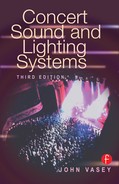
To find the total resistance in a series circuit, simply add together all resistors. In other words, a 10-ohm, a 150-ohm, and a 1,000-ohm resistor connected in series would equal a single 1,160-ohm resistor. The formula is shown in Figure B–1.
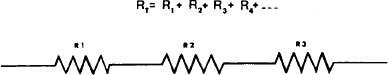
Figure B–1. Formula to define resistance in a series circuit.
RESISTORS IN PARALLEL
Resistors in a parallel circuit are a little more difficult. The formula for two resistors in parallel is as follows:
![]()
For more than two resistors in parallel, the formula is given in Figure B–2.
CAPACITORS IN SERIES
Capacitors in series are similar to resistors in parallel in that one adds the reciprocals. The formula for two capacitors in series is as follows:
![]()
The formula for more than two capacitors in series is shown in Figure B–3.

Figure B–2. Formula to define total resistance.

Figure B–3. Formula for more than two capacitors in series.
CAPACITORS IN PARALLEL
Capacitors behave in direct contrast to resistors. When capacitors are in parallel, use the formula shown in Figure B–4.
POWER IN A CIRCUIT
When current passes through a component, energy is given off in the form of heat. Resistors normally are associated with this action because it is part of their purpose. When it is necessary to know how much power a resistor is giving off, use the following formula:
W = EI
where W is in watts, E is in volts, and I is in amperes.
CABLE WIRING
There is no common standard of wiring for concert equipment. It is important to check the wiring standard and color coding of any connecting cables being used, whether they carry signal level, speaker level, or power (Figure B–5).
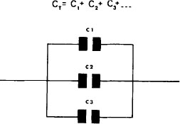
Figure B–4. Formula for capacitors in parallel.
An incorrectly wired cable can destroy the performance of an entire sound or lighting system. A faulty cable is potentially dangerous; take special care when handling main power cables and connectors. Most consoles have phase-reverse switches so that they can accommodate any standard of wiring for inputs. Phasing must be consistent throughout the system so that no phase cancellation occurs. The wiring standards for all equipment in use must be established and a record kept with the equipment for reference.
Figure B–5. Audio cable connector wiring. Standard wiring method for audio signal cables. (Courtesy Yamaha Music.)