Chapter 2
Network Infrastructure
Introduction
More often than not, wireless engineers or any other people interested in wireless tend to focus only on the wireless side of things, because it is what started their passion for networking in the first place. However, it is precisely because an access point is a device bridging 802.11 wireless frames to 802.3 Ethernet frames, and vice versa, that a good wireless administrator will need to be proficient in configuring the wired infrastructure to support the wireless network. The best designed wireless infrastructure will perform very poorly if there is poor design, planning, or configuring on the wired side of things. In many other cases, certain types of wireless traffic will simply not work or flow because of misconfigurations on the infrastructure side. Wireless CCIEs are not required to have the same proficiency in routing or switching as an R&S CCIE but they should be able to discuss effectively with one another and understand the technologies and challenges.
This chapter covers the technologies that are involved in providing a stable wireless network. Each section provides information on a specific technology or protocol. This chapter does not cover each of those protocols and technologies in every detail, nor does it cover each of their settings and darkest tweaks. It also does not cover every type of switch or routing device that you may encounter in the real world. Instead, it focuses on the devices used in the CCIE Wireless blueprints and will give you the foundations to adapt to other network devices, if you need to do so. However, it gives an introduction and “deep enough” understanding for a CCIE Wireless candidate to become proficient in configuring those devices in order to set up a well-performing wired infrastructure that will support a well-performing wireless network.
At the end of this chapter, you should have a good understanding of the technologies involved in configuring and optimizing a wired network to support a good wireless infrastructure.
Switching Technologies
We first focus on technologies that revolve around Layer 2 before moving higher up in the OSI model layers.
VLANs
A lot can be said about VLANs, and chances are that if you are reading this, you must have an idea or two about how to use them. What are the VLANs pros and cons with regard to wireless, though? Are the guidelines the same as for a fully wired network? Let’s see.
A VLAN, basically, is a (virtual) Layer 2 network or subnet within your physical topology. A VLAN defines a broadcast domain—that is, all the links where broadcasts emitted in that subnet will be sent through. It is important to realize that clients will broadcast for ARP in IPv4, for DHCP, but also for a large amount of discovery protocols depending on their operating system. A lot of services discover compatible devices through same-subnet broadcasts (or multicast, which will also be spread across the VLAN). This represents a lot of traffic, and VLANs are here to help reduce the size of the domain of those broadcasts. Each VLAN will also typically require a gateway for hosts to reach out to other subnets. This gateway can be configured on a switch or a router in the network, where some VLAN interfaces are centralized.
You can configure a switchport to be in access mode; it is then mapped to a specific VLAN statically. No VLAN tags on the frames are used with this method. You can therefore connect a host or PC (which typically are not VLAN aware) to such a switchport, and the switch will automatically consider that all traffic coming from this port is mapped to the specified VLAN. It will then be forwarded accordingly only to ports where that VLAN is configured (until a gateway routes the packet, possibly).
Switch1(config)# interface Gig0/1
Switch1(config-if)# switchport mode access
Switch1(config-if)# switchport access vlan 20
The preceding is traditionally used to configure ports where hosts or end devices connect. However, links between infrastructure switches will often have to carry several VLANs. This is where the switchport mode trunk kicks in.
Switch1(config)# interface Gig0/2
Switch1(config-if)# switchport mode trunk
Switch1(config-if)# switchport allowed vlan 1-10
The previous commands configure the port to trunk mode and allow only VLANs 1 to 10 through it. Other VLANs will not be allowed to cross the link. If you do not specify the allowed vlan command, all VLANs will be allowed by default (although this may vary depending on the platform). In the past, there were several ways to implement VLANs and several protocols to achieve this function, but nowadays the standard 802.1Q is the only way to go. As shown in Figure 2-1, it is a header present (only on trunk ports) at the Layer 2 level.

It is good practice to always restrict the VLANs of a trunk to the required VLANs, to avoid unneeded broadcasts traveling insane distances. A trunk port by default will use VLAN 1 as native, which means that all frames in VLAN 1 will not have any 802.1Q encapsulation header. It also means that the switchport will consider all non-802.1Q tagged traffic it receives to belong to VLAN 1. This native VLAN can be changed with switchport trunk native vlan <id>. It is important that both ends of a trunk port consider the same VLAN to be the native; otherwise, you will be bridging two different VLANs together. Indeed, if the first switch sends a frame in VLAN 5, and VLAN 5 is the native for that switch, the frame will be sent without any 802.1Q tag. If you then imagine that the connected switch is configured to consider VLAN 1 as the native, and it receives an untagged frame, it will consider it to belong to VLAN 1 and will bridge it accordingly. So, care needs to be taken when deciding which VLAN will be the native VLAN for your trunk ports.
For a VLAN to work on a given switch, it must be created first. It is also a typical catch if you create a Switch Virtual Interface (SVI; that is, a Layer 3 interface) for a given VLAN and the SVI does not come up. Verify the VLAN database (with show vlan) and, if it’s missing, create it (setting a name is optional):
Switch1(config)# vlan 10
Switch1(config-vlan)# name marketingvlan
On the wireless side of things, lightweight access points require an access mode switchport unless FlexConnect local switching is being used, which typically requires a trunk mode switchport because you are likely to use more than one SSID/VLAN (but it’s not a hard requirement otherwise). Autonomous access points support both; it all depends on how many VLANs you configure the access point to support.
From a design perspective, it is important to understand that a WLC will automatically, by default, stop broadcasts. It acts as an ARP proxy and DHCP proxy to unicast just the right client and drastically reduces the amount of broadcast traffic in the VLAN. This allows for much larger subnets for wireless clients. On the other hand, it is important to still be cautious of the number of broadcasts spreading around your VLANs in case you have many wired devices (including APs) in the same VLAN.
Table 2-1 includes your go-to commands when suspecting a VLAN-related issue on a switch. They will show you which VLANs exist and which VLANs are allowed on ports.
Table 2-1 show Commands Helpful in Analyzing the VLAN Situation on a Switch
Command |
Purpose |
switch# show interface trunk |
Displays all active trunk ports, their native VLANs, and VLANs currently active on them |
switch# show vlan |
Shows the VLAN database with all the VLANs existing on that particular switch, along with the ports where they are active |
Private VLANs
You can configure private VLANs to further isolate subdomains in a given VLAN. When configuring a private VLAN on a switchport, the devices behind that port will be able to communicate only with the gateway and not spread Layer 2 broadcasts to other ports on that switch in the same VLAN. It is also possible to carry the private VLAN information between several switches supporting it, to create a subdomain within a given VLAN where devices can communicate directly at Layer 2 (those devices will have to use the gateway for outside communication, though). There will be a mapping between a primary VLAN (a VLAN as we have defined it so far) and secondary VLANs (private VLANs) that will exist within that VLAN on switches supporting this.
There are two types of private VLANs: isolated and community. An isolated secondary private VLAN can only communicate toward the primary VLAN (and thus its gateway). A community secondary private VLAN can communicate to other hosts in the same secondary VLAN as well as the primary VLAN, but cannot communicate to other secondary VLANs. A PVLAN port can be configured in promiscuous mode or host mode. Promiscuous mode ports will allow communication from several (defined) secondary and primary VLANs. Host mode ports will allow traffic only from specific secondary VLANs to promiscuous ports or host ports in the same community PVLAN. Figure 2-2 illustrates the host port versus promiscuous ports behavior difference.

Private VLANs are useful when you want to segregate devices but still have to use the same VLAN (and therefore subnet and SVI). In the next example, we are configuring VLAN 10 to be the primary, and within it, we will have secondary VLAN 200 in community mode and 300 in isolated mode. Port Gig0/1 will be set in promiscuous mode and will allow traffic from both private VLANs 200 and 300 to flow. Figure 2-3 illustrates the community mode behavior.

Example 2-1 Configuring Private VLANs
Switch1(config)# vlan 10
Switch1(config-vlan)# private-vlan primary
Switch1(config-vlan)# exit
Switch1(config)# vlan 200
Switch1(config-vlan)# private-vlan community
Switch1(config-vlan)# exit
Switch1(config)# vlan 300
Switch1(config-vlan)# private-vlan isolated
Switch1(config-vlan)# exit
Switch1(config)# vlan 10
Switch1(config-vlan)# private-vlan association add 200,300
Switch1(config-vlan)# exit
Switch1(config)# interface Gig0/1
Switch1(config-if)# switchport mode private-vlan promiscuous
Switch1(config-if)# switchport private-vlan association mapping 10 200,300
Switch1(config-if)# interface Gig0/2
Switch1(config-if)# switchport mode private-vlan host
Switch1(config-if)# switchport private-vlan host-association 10 200
Table 2-2 show Commands Relating to Private VLANs
Command |
Purpose |
switch# show vlan private |
Displays all the private VLAN information along with their primary VLAN mapping and active ports |
switch# show vlan |
Shows the VLAN database with all the VLANs existing on that particular switch along with the ports where they are active |
VLAN Trunking Protocol
As we already briefly mentioned, a well-managed network only allows for the needed VLANs on any link, to prevent unrequested broadcasts from spamming your network unnecessarily. However, VLANs must exist in the VLAN database of all the switches they will cross. It is easy to envision how painful the addition of a new VLAN or subnet will be. You create a VLAN on a switch, map a switchport to it, allow it on your uplink trunk, and you think you’re done for the day—only to realize later that traffic is not passing further down the network because you did not create that same VLAN on another switch that is on the traffic path.
This is where VLAN trunking protocol (VTP) comes to the rescue. The following explanations (unless specifying the particular version) focus on VTP version 2. We also cover the differences with VTP version 3 right after. One of your switches will function as a single source of truth and will update other switches in the VTP domain about the VLANs in operation. The domain is a group of switches sharing VLAN information under a 32-character identifier. The switch operating in server mode can add, delete, or rename any VLAN, and the configuration will be saved in the NVRAM. In client mode, the switch will receive its VLAN information from the VTP server and will use this for its VLAN database. The administrator will not be allowed to make modifications to the client switches VLAN database. One last VTP mode is the transparent mode, in which the switch does not participate in VTP (that is, does not “install” the VTP information passed in its database) but will allow the propagation of that VTP information to switches further down the path. In transparent mode, the administrator can make changes to the VLAN database on that transparent mode switch. These modes are illustrated in Figure 2-4.

To configure VTP, you need to set the VTP version (it must match on all switches) and the VTP domain as well as the switch mode. It is also a requirement to have a trunk port configured on the switch (VTP only propagates on trunk ports, not access) and for all VTP switches to be directly adjacent.
Every time the VTP server switch has a new VLAN configuration change, it will increment its configuration revision number (starting at 0). Client VTP switches will update their database only if the received VTP revision is higher than their current revision number. This prevents old VTP data from continuing to propagate and corrupt the configuration. This can also prevent the situation in which a test switch (with low revision count) connects to the production network overriding all the VLAN configuration. This is also important to keep in mind in case your configuration looks good but you don’t see your VTP clients using any of the server information; if you have played with the VTP clients before or changed their roles, they might have a higher revision count at that moment in time (and therefore are not accepting the latest server update). Note that having more than one VTP server in the same network is also allowed. They will sync their revision numbers, and any new revision caused by a configuration change on one of the servers will immediately be installed on all the other switches (including servers) and increment their revision number.
VTP has several versions. Version 1 and 2 are similar and support only VLANs from 1 to 1024. VTP version 3 supports 4000 VLANs. VTP version 3 will propagate updates to VTP version 2 clients but not the other way around, so it’s best to match the versions everywhere as much as possible. Version 3 also supports private VLANs, adding protection from unintended database override during the insertion of a new switch, configuration options on a per-port basis, and clear-text or hidden password protection. It also not only transfers the VLAN database, but also the MST (spanning-tree) database. A switch in transparent mode, even if using VTP version 1 or 2, will properly forward version 3 updates containing all these new features. Example 2-2 shows a small example of a basic VTP configuration.
Switch1(config)# vtp domain CCIE
Configures the VTP domain to the string "CCIE"
Switch1(config)# vtp password topsecretpassword
Optionally configures a password (it can be secret or hidden only in v3)
Switch1(config)# vtp version 2
Configures version 2 of VTP
Switch1(config)# vtp mode server
Configures the mode (server, client or transparent)
Switch1(config)# vtp interface VlanY
By default, vtp uses the lowest-numbered vlan interface to source VTP updates. In
case that vlan is not allowed through to all neighboring switches, you may have to
specify that source interface yourself
Table 2-3 shows the basic commands that will allow you to verify and validate a VTP configuration.
Table 2-3 show Commands Related to VTP Configuration Verification
Command |
Purpose |
switch# show vtp interface |
Displays all the interfaces of the switch and whether VTP is enabled for those interfaces (enabled by default on all interfaces; you can do “no vtp” on a given interface to disable it there) |
switch# show vtp status |
Shows all VTP-related information (domain, version, mode, configuration revision) |
switch# show vtp devices |
Displays information about all VTP version 3 devices in the domain |
Spanning Tree Protocol
If a loop exists in a network in such a way that a frame can be received by a device after it sent that same frame, all hell breaks loose. This would happen (if there was no spanning tree) as soon as more than one single link exists between two given devices in the network. It would cause not only duplicated frames and out-of-order packets, but also switches would learn the same MAC address alternating between different ports (also referred to as “flapping”). The loop would also cause endless traffic as broadcasts (or frames sent to multiple destination ports) would create traffic that never stops until its time to live (TTL) expires (if there is one; not all frames have a TTL).
The purpose of the Spanning Tree Protocol (STP) algorithm is to form a tree with the network topology. There is one root node, and from there, only leaves: there are no more than a single path to any leaf, and all leaves can reach out to each other if going back through the root and the whole structure is loop free.
This root node, called the root bridge (because switches are bridges originally) is elected based on the Bridge ID (BID), which is a mix of a 2-byte priority field combined with the MAC address. In STP, the lower value is preferred to become the root bridge. In a default configuration, the priority field is 32768 and is the same on all switches. The root is therefore chosen solely based on the lowest MAC address. Interfering with this election process is as simple as lowering the priority value on the switch you want to become root. Each switch will calculate the path cost to the root through all their possible ports. If only one port leads to the root bridge, it will be elected the root port for that switch; if more than one port leads to the root, then the one with the shortest (that is, lowest cost) will be chosen as the root port. A specific cost is associated to each link bandwidth (a 10 Gbps link has much smaller cost than Fast Ethernet, for example). In case of identical path cost, the lowest port ID is chosen. All other ports leading to the root (apart from the root port) will be put in blocked state to avoid loops.
Each switch sends STP messages called BPDUs as a Layer 2 multicast. Ports connecting to end devices do not receive BPDUs; therefore, the switch knows there is no path to the root through those, and they can be in forwarding state.
The various STP states are the following:
Blocking: A port is always in blocking mode when it comes up (to avoid issues), and it stays in blocking state if the switch detects it leads to the root bridge but is not the most optimal path.
Listening: When a port is in listening state, it listens for other switches or bridges. It does not send anything; it only listens.
Learning: The switch keeps listening for other bridges but can also learn MAC addresses on that port.
Forwarding: Normal operation mode. Data and BPDUs are passed through the port.
The main STP timers are the Hello timer, the Maximum Age, and the Forward Delay. The Hello timer means that the switch will send a BPDU every 2 seconds by default. The max age of 20 seconds by default determines the time for which the port is kept in a blocking state before listening. The forward delay of 15 seconds by default means the port will stay for 15 seconds in the listening state before moving to the learning state, and the same amount of time between the learning state and the forwarding state. Technically, this means that a port will not be forwarding traffic for 30 seconds after it is brought up.
Similar to the states, there can be three port types that STP will set on a given switch:
Root: Only one per switch. This port is the most optimal path to the root bridge.
Designated: This port is forwarding; there is a designated port for each LAN segment to reach.
Alternate (non-Designated): This port is blocked. It is a suboptimal path to the root. In case of failure of the root port, one of the alternate ports will become the root port.
Figure 2-5 illustrates the different STP port types.

The only device that doesn’t have any of its ports in the root status is the root bridge.
Rather than modifying the priority of the bridge ID to influence the root bridge election, you can use commands to do it for you:
Switch1(config)# spanning-tree vlan X root primary
Switch2(config)# spanning-tree vlan X root secondary
These commands influence the priority so that Switch1 will lower its priority to be the root when it is online, and Switch2 will become the root if Switch1 is not present. They are useful in making sure your backbone, or most powerful switch, is the root rather than a smaller access switch. In case you want to set priorities manually, you can use spanning-tree vlan <vlan id> priority <priority value>, but bear in mind the root commands are macros and don’t guarantee the switch will always be root regardless of what further priorities show up on the network.
There are also situations where a device has two or more uplinks to interconnected backbone switches, and you want to determine which link will be in the forwarding state and which one will be blocked, rather than letting STP decide.
Switch1(config)# interface Gig0/1
Switch1(config-if)# spanning-tree port-priority 0
Switch1(config-if)# interface Gig0/2
Switch1(config-if)# spanning-tree port-priority 240
The lower the port priority, the better. In the previous example, it means that port Gig0/1 will be forwarding rather than Gig0/2 if they both were candidates for root port with equal cost until then. Valid priority values are increments of 16: 0, 16, 32, 48, 64, 80, 96, 112, 128, 144, 160, 176, 192, 208, 224, and 240. The default is 128.
STP also allows the configuration of path cost, which is directly tied by default with the interface bandwidth. If port priorities are the same, the cost is the deciding factor.
Table 2-4 lists show commands that will help you have an overview of the current spanning tree status.
Table 2-4 show Commands Related to Spanning Tree Troubleshooting
Commands |
Purpose |
show spanning-tree active |
Displays spanning tree information on active interfaces only. |
show spanning-tree detail |
Displays a detailed summary of interface information. |
show spanning-tree vlan vlan-id |
Displays spanning tree information for the specified VLAN. |
show spanning-tree interface interface-id |
Displays spanning tree information for the specified interface. |
show spanning-tree interface interface-id portfast |
Displays spanning tree portfast information for the specified interface. |
show spanning-tree summary [totals] |
Displays a summary of interface states or displays the total lines of the STP state section. |
show spanning-tree blockedports |
Displays all the alternate ports that are blocked currently. |
We have only covered basic spanning tree in this section so far. Historically, many devices have been running Per-VLAN Spanning Tree (PVST) or variants of it, such as Rapid PVST. With such a method, one completely separate instance of the Spanning Tree algorithm runs on each VLAN the switch knows. Therefore, from the command spanning-tree vlan 30,40 root primary, you can figure out that there can be different root bridges in each VLAN and that a different election and different tree is built for each VLAN in the network, which can be very resource-consuming if you have many VLANs in your network.
Rapid PVST is a backward-compatible evolution of PVST that allows for a much faster convergence (within 1 second, compared to 30–50 seconds with the standard PVST).
STP Tuning Commands
The first and most important STP optimization command is spanning-tree portfast. This command is to be typed on edge ports only, where no loop can happen and only client devices connect. A link failure on such a port should definitely not trigger any STP topology changes. When the command is configured, the port is immediately moved to the forwarding state when it comes up. This is a best practice to configure on ports (in switchport access mode) where unified access points in central switching are connected. Access points have only clients connecting to them; they should never receive BPDUs over the air and will not cause any STP topology changes. Therefore, this command allows AP switchports to immediately come up and into the forwarding state. A variation of it is spanning-tree portfast trunk. Whereas a trunk typically indicates a connection to another switch, it can also be used for access points in autonomous modes or FlexConnect local switching. In this case, the spanning-tree portfast command will have no effect, and you must use spanning-tree portfast trunk instead because the switchport is in trunk mode.
BPDU Guard is a good complementary measure for portfast ports. When enabled, BPDU Guard shuts down the port (technically it moves it to err-disabled, and you can configure recovery options) when it receives a BPDU. It is a secure response to an invalid and unexpected event. Always keep in mind that portfast ports are supposed to be connected to end devices and should not be used to connect a switch, because this would create a loop (since the portfast port is moved to forwarding state instantly). In such a situation, BPDU Guard will prevent this from happening by shutting down the port, as illustrated in Figure 2-6. When enabled globally, BPDU Guard will apply to all interfaces with portfast configuration.

BPDU filtering can be done globally on all portfast ports or on a per-port basis. It will prevent the switch from sending or receiving BPDUs on those ports. In case a BPDU is received on a regular portfast port, the port loses its portfast status and becomes a normal STP port. Therefore, BPDU filtering is dangerous and can be a cause for unhandled bridging loops because the port will keep forwarding even if you plug another switch to it (because it is configured to drop all BPDUs it receives).
EtherChannel guard will detect when interfaces are configured for EtherChannel on the local switch but not on the other end of the links (or in invalid configuration on the other end). To prevent a loop, it will set the interfaces to err-disabled state.
Root guard prevents a port from becoming root port or alternate blocked port. If a port configured for root guard receives a superior BPDU, it will immediately go to the root-inconsistent blocked state, as shown in Figure 2-7.

Loop guard will help detect unidirectional link failures. As soon as a root or alternate port stops receiving BPDUs from the other end of the link, it will transition to the loop-inconsistent blocking state, assuming there is an error on the link (it may be up, but we are not receiving BPDUs anymore from the other side, so something is definitely fishy).
Multiple Spanning Tree
An evolution of Rapid PVST is Multiple Spanning Tree (MST). Having one instance of STP per VLAN is very resource consuming, and MST solves this by having one MST instance run for several (typically an unlimited amount of) VLANs at a time. MST also allows for multiple forwarding paths for data traffic and load balancing. MST is backward compatible in a network with devices doing PVST or Rapid PVST. You can change the spanning tree mode with the command spanning-tree mode mst.
Switches will form an MST region and participate together if they have the same VLAN-to-instance mapping, the same configuration revision number, and the same name. A VLAN can belong to only one MST instance (to prevent conflicting decisions).
Switch1(config)# spanning-tree mst configuration
Switch1(config-mst)# instance 1 vlan 5,10-20
Switch1(config-mst)# name region1
Switch1(config-mst)# revision 1
Switch1(config-mst)# exit
Switch1(config)# spanning-tree mode mst
Switches will start the MST instance as soon as the spanning-tree mode mst command is entered.
Commands will be similar to PVST; for example, spanning-tree mst 1 root primary will configure the switch to be the root bridge in all the VLANs covered by instance 1. Similar commands exist to other modes and are preceded by the MST instance ID. You can also configure several MST instance IDs by using commas or hyphens.
Spanning Tree and Wireless
We already covered that access points should always be on switchports configured with spanning-tree portfast. WLCs don’t participate in spanning tree or send BPDUs. Because they should never create a loop (whether APs are in local mode or FlexConnect), and because it is a front end for clients and no other network devices, it is recommended to set the WLC port as a portfast trunk as well. Note, however, that there may be an exception revolving around Mesh Ethernet bridging or workgroup bridging where you may end up with a switch being connected behind a wireless client. In this particular instance, it is up to the administrator to make sure there will not be a loop (that is, the remote bridged site should not have a wired connection to the root side) and that BPDUs are not sent over the air.
EtherChannel
EtherChannel, also referred to as portchannel, is a widespread technology in wireless networks. It answers several questions:
How can I leverage an existing infrastructure to get more bandwidth on a link between these two devices without upgrading to the next Ethernet standard? (Two times 1 Gbps links is sometimes cheaper or more easily implemented due to hardware limitations than a single 10 Gbps link or, similarly, two times 10 Gbps rather than a single 40 Gbps, for example, and might just fit the need.)
How can I get more reliability in case a link goes down due to port or cable failure?
The now legendary Cisco 4404 WLC had four 1 Gbps ports at a time when 10 Gbps was still expensive and not particularly widely available on core campus switches. Today, the 8540 WLC has four 10 Gbps ports for the very same reasons. (10 Gbps has become more affordable and widespread, whereas 40 Gbps is not quite there yet.) On top of the increased bandwidth, EtherChannel also provides link redundancy: when one of the links forming the EtherChannel goes down, the others keep forwarding, and the only impact is decreased overall bandwidth (that faulty link can’t be used anymore until the cable is replaced or other fault fixed). This is illustrated in Figure 2-8.

If you don’t use EtherChannel and set up several physical links between the same two network devices, spanning tree will do its job and block all but one link to avoid loops, as shown in Figure 2-9. There is no increased bandwidth involved because only one link is used at a time, and the spanning tree algorithm will be the one deciding which other link will come up after the active link goes down. The redundancy is, therefore, slightly less real-time because it’s another link that has to come up. With EtherChannel, you are grouping physical interfaces together, therefore creating a virtual portchannel interface that will represent all the links as a single one from that point on. This single virtual portchannel interface means that for STP, all links participating in the portchannel are now seen as a single link and therefore are set to forwarding or blocked all together as one. It also means that you can (and actually must) from there on configure all those links only through the virtual portchannel interface rather than through the specific physical interfaces. The portchannel interface configuration will be applied to all ports participating in the portchannel bundle.

There are a few restrictions though. EtherChannel can only be configured between a maximum of 8 ports of the same speed and technology (all GigabitEthernet or all TenGigabitEthernet, but no mix-and-match). Each end of an EtherChannel link must also be configured in the same way.
A careful reader will immediately ask how loops are prevented, because all the physical links constituting a portchannel are up and forwarding at the same time, and STP sees them as only one link. The answer is the load balancing algorithm. The switch(es) where EtherChannel is configured will use a configurable algorithm to make sure packets of the same flow will always go through the same physical port. This prevents out-of-order packets or fragmentation issues in an easy and practical manner. A classical method for wireless networks is to declare that all packets from the same source and destination IP pair will go through the same link. This means that a specific access point will always send its traffic through the same link when sending to the WLC, but another access point might use another physical link. This is completely transparent to the end devices because only the two devices participating in the EtherChannel bundle are aware and must agree on this method.
You have three methods of configuring an EtherChannel:
By using PAgP negotiation protocol
By using LACP negotiation protocol
By turning it always on without negotiation
The same method should be used on both ends of an EtherChannel in all cases. PAgP is a Cisco proprietary protocol that will verify whether the parameters are identical on both ends before enabling the EtherChannel. This is configured with the command channel-group <etherchannel number> mode desirable (where X is to be replaced with the EtherChannel group number). PAgP is not supported with WLCs.
LACP is an IEEE specification that allows a switch to negotiate an automatic bundle by sending LACP packets to the other side. This mode can be enabled by using channel-group <etherchannel number> mode active. It is not supported for use with WLCs but is supported for use with select 802.11ac Wave 2 access points having an AUX port.
When configuring with channel-group <etherchannel number> mode on, the EtherChannel is established without any form of negotiation. This mode is the only one that can be used with WLCs.
The configuration guidelines are as follows:
EtherChannel support: All interfaces must support EtherChannel. They can be of different media type and on different modules but on the same switch, even if virtual, such as in a VSS.
Speed and duplex: All interfaces configured must operate at the same speed and duplex mode.
VLANs: All interfaces configured in the EtherChannel must be assigned to the same VLAN or must be configured as trunk, before joining an EtherChannel. If trunk, they must support the same range of VLANs.
Example 2-3 shows how to configure interfaces Gig0/1 and Gig0/2 into a LACP portchannel allowing VLANs 1 to 10. After the portchannel is created, further configuration changes will happen directly in the portchannel interface.
Example 2-3 Configuring LACP-enabled Portchannel Interface
Switch1(config)# interface Gig0/1
Switch1(config-if)# switchport mode trunk
Switch1(config-if)# duplex auto
Switch1(config-if)# switchport trunk allowed vlan 1-10
Switch1(config-if)# channel-group 1 mode active
Switch1(config-if)# exit
Switch1(config)# interface Gig0/2
Switch1(config-if)# switchport mode trunk
Switch1(config-if)# duplex auto
Switch1(config-if)# switchport trunk allowed vlan 1-10
Switch1(config-if)# channel-group 1 mode active
Switch1(config-if)# exit
Switch1(config)#
At this stage, we have created a new virtual interface called Portchannel1. If we want to add a VLAN to the trunk or change any setting later on, we have to do it only in the Portchannel1 interface, and not in the physical interfaces anymore.
For example, to add VLAN 11:
Switch1(config)# interface Portchannel1
Switch1(config-if)# switchport trunk allowed vlan add 11
Don’t forget to configure the same commands on the other switch! The ports could be different on the other switch. We could decide to put Gig1/2 and Gig 2/5 on switch2 into Portchannel5. As long as they connect to two ports on switch 1 that are on a portchannel with the same settings, all is well.
Table 2-5 shows some useful commands to verify the EtherChannel settings.
Table 2-5 Commands to Verify EtherChannel Settings
Command |
Purpose |
switch# show interface port-channel channel-number |
Displays the status of a portchannel interface. |
switch# show lacp { counters | interface type slot / port | neighbor | port-channel | system-identifier } |
Displays LACP information. |
switch# show port-channel compatibility-parameters |
Displays the parameters that must be the same among the member ports to join a portchannel. |
switch# show port-channel database [ interface port-channel channel-number] |
Displays the aggregation state for one or more portchannel interfaces. |
switch# show port-channel load-balance |
Displays the type of load balancing in use for portchannels. |
switch# show port-channel summary |
Displays a summary for the portchannel interfaces. |
Anticipating further chapters, let’s underline that if you are using LAG on a WLC, you should have only one interface marked for “Dynamic AP management,” but if you don’t use LAG, you should have one interface with “Dynamic AP management” enabled on each physical port of the WLC.
It is also possible to configure LAG between a switch and a Wave2 access point (provided it has an AUX port) like the 1850, the 2802, or the 3802 (because they have an AUX port). The problem would be that because all the traffic is tunneled to the WLC through the CAPWAP data tunnel, it would be hard to load balance anything between the two ports. This is why, when enabling LAG, those access points establish a second CAPWAP data tunnel to the WLC using another source port. The switch can then use the command port-channel load-balance src-dst-port as a load-balancing mechanism to load balance the traffic between the two AP ports. This, however, is not yet supported in FlexConnect local switching. If the switch does not support Layer 4 (port) load-balancing, there will be redundancy, but all the traffic will go through a single port.
After the AP registers to the WLC, run the following commands from the WLC command line:
config ap lag-mode support enable
(This will NOT result in a reboot of the APs that support LAG)
This command enables the support for AP LAG mode globally on the WLC. To check the current status of the AP LAG mode support on the WLC, run the command show ap lag-mode. To disable support for AP LAG mode, use config ap lag-mode support disable (this will result in a reboot of all the APs that support LAG).
config ap lag-mode support enable <AP name>
(This will result in a reboot of the AP)
This command enables LAG mode support on the AP itself. When you enable this command, in the show ap config general <AP name> command you will see that the AP LAG config status has been changed to “enabled” from “disabled”.
AP LAG Configuration Status ..................... Enabled
To disable LAG mode on the AP use config ap lag-mode support disable <AP name> (this will result in a reboot of the AP).
Access points support LACP or “mode on.” Because one of the requirements is that all ports of an EtherChannel are of the same Ethernet type, it is not possible to bundle an mGig port with a GigabitEthernet port in an EtherChannel. The mGig can be configured to 1 Gbps to make this work.
CDP and LLDP
Cisco Discovery Protocol (CDP) is a Layer 2, media-independent and network-layer independent protocol that runs on Cisco devices and some third-party devices as well (although it is Cisco proprietary) that allows devices to learn what is directly connected to them. Each device configured for CDP periodically sends advertisements to the multicast MAC address 01:00:0c:cc:cc:cc. By listening for this MAC address, the device will also learn about CDP-enabled devices that are directly connected to it. CDP is not forwarded by Cisco devices; therefore it is only point-to-point and does not travel through the network. CDP information includes the following:
Cisco IOS version running on Cisco devices
Hardware platform of devices
IP addresses of interfaces on devices
Locally connected devices advertising Cisco Discovery Protocol
Interfaces active on Cisco devices, including encapsulation type
Hostname
Duplex setting
VLAN Trunking Protocol (VTP) domain
Native VLAN
CDP allows for detection of native VLAN mismatch on trunk ports and is very helpful in troubleshooting to understand the physical network topology.
Link Layer Discovery Protocol (LLDP) is a similar standard protocol that will perform the same kind of functions as CDP but will bring compatibility with third-party devices that are more likely to support LLDP than CDP. LLDP-MED is a Media Endpoint Device extension for LLDP, which adds more capabilities with regard to power management and network policies.
CDP neighbors can be verified both on the switch or on the AP with the show cdp neighbors command. On a switch, you can enable CDP globally with the configuration-level command cdp run. It is then enabled by default on all interfaces. You could disable it on a given interface with no cdp enable under that specific interface. LLDP works in a similar manner and can be enabled with the global command lldp run. You can then enable it for a specific interface with lldp transmit and lldp receive commands. show lldp neighbors will give you the LLDP neighbor. Example 2-4 shows the CDP neighbor output showing an access point along with the power levels it requested (refer to the next section for PoE with CDP):
Example 2-4 Output of show cdp neighbor details on a Port Where an Access Point Is Connected
switch# show cdp nei det
-------------------------Device ID: APd46d.50f3.7a27
Entry address(es):  IPv6 address: FE80::D66D:50FF:FEF3:7A27  (link-local)
Platform: cisco AIR-CAP2602I-E-K9,  Capabilities: Trans-Bridge Source-Route-Bridge IGMP
Interface: GigabitEthernet0/8,  Port ID (outgoing port): GigabitEthernet0Holdtime : 160 sec
Version :Cisco IOS Software, C2600 Software (AP3G2-K9W8-M), Version 15.3(3)JF5,
  RELEASE SOFTWARE (fc2)Technical Support: http://www.cisco.com/techsupportCopyright
  (c) 1986-2018 by Cisco Systems, Inc.Compiled Mon 29-Jan-18 23:21 by prod_rel_
  teamadvertisement version: 2
Duplex: fullPower drawn: 15.400 Watts
Power request id: 8446, Power management id: 12
Power request levels are:15400 13000 0 0 0
We have already hinted that CDP (or LLDP) will be used in providing power to Cisco APs, but it is also very useful for quickly locating on which port access points are connected (through the CDP neighbor table), identifying what their IP address currently is, and what model and software version they are running. The WLC supports CDP (but not LLDP) and can provide a list of its CDP neighbors to verify the switchport connections (see Table 2-6).
Table 2-6 CDP-Related Commands on the WLC
Command |
Purpose |
WLC> show cdp neighbor |
Displays the list of WLC CDP neighbors. |
WLC> show ap cdp neighbors all |
The WLC also receives information from the APs with regard to their CDP neighbors. This is useful to verify on which switch(port) an AP is connected, straight from the WLC command line. |
Power over Ethernet for Access Points
Power over Ethernet is a very handy technology for powering access points, because it allows you to run only one network cable to the AP location, instead of an extra power cable (and power supply, which would need to be tied up properly and which might heat, and so on). Things were a bit more complicated in the past with prestandard technologies, but for the purposes of this book, let’s focus on the 802.3af PoE standard that allows up to 15 watts and the 802.3at standard (often referred to as PoE+) that allows up to 30 watts to the device. Some outdoor APs require a bit more than 30 watts and have to rely on UPoE, which can provide up to 60 watts, but that is not yet an IEEE standard (at the time of this writing and will be superseded eventually by 802.3bt, which promises 90 watts). In any case, at present, most APs don’t require that much power. Each AP has different power requirements:
A 3600 will operate at full capacity with 15 watts 802.3af PoE.
A 3700 will require PoE+ to fully operate because it consumes up to 16.8 watts. However, it can operate in “medium power” with a standard 802.3af (15 watts) and will then power off one antenna (3×3 MIMO instead of 4×4).
A 3800 will require 802.3at to operate, with no “medium power” available at all.
Those are just examples of how things differ with each AP model. Some APs will be able to boot when given insufficient power (802.3af instead of 802.3at, for example) but will keep the radios completely down, allowing you to spot the problem and remediate it.
PoE is most practical when the switch supports it and can deliver the power to the device connected without any form of particular intervention. When a cable is plugged in, there is a physical detection mechanism (based on impedance detection) that can figure out whether the connected device supports PoE. This detection has to happen when the device is still powered off and is required to prevent the switch to send power to a device not supporting power on the Ethernet port (which would otherwise most probably burn it). There are predefined watts requirement “steps” that can be detected this way. After the device has booted, it is also possible for a more granular power negotiation to occur. This can take place through CDP or LLDP (LLDP is not Cisco proprietary; neither is the 802.3at standard). The end device may then require the exact amount of wattage it will require through this more dynamic protocol. Devices exchange TLVs with their capabilities and negotiate the power. After an AP has gone through this negotiation phase, any change of power provided will make the AP reboot.
When the switch does not support PoE, the alternative is to use a power injector. The injector is a small brick that plugs in to an AC power socket and has typically 2 RJ45 ports: one that connects to the switch (to provide network connectivity to the AP) and the other to connect to the AP. The power injector basically sits between the AP and the switch, tries to stay invisible, and just adds power on the network cable while it forwards the data back and forth. Power injectors also exist with fiber uplinks and other variations where they may also have other names, but the same basic concept remains. Figure 2-10 shows the AIR-PWRINJ6, the 802.3at-compliant power injector recommended for use with 802.11ac wave2 access points.

A very important notion in PoE is the Power Sourcing Equipment (PSE) power budget. When the PSE is a power injector, it typically provides power for only one device, the powered device (PD), and therefore the concept of budget is a bit irrelevant. But when the switch is the PSE, it becomes apparent that the switch cannot provide an unlimited amount of power through all its ports. Some switches have a power budget as small as 30 watts (providing PoE+ on one single port, but maybe regular PoE on two ports, or even more if the devices consume less than 15 watts) and can go up in the hundreds of watts for bigger switches. In any case, depending on the number of devices connected to the PSE and the power that they are currently consuming, there is only a certain power budget left for new devices. If the power budget for that switch has already been exhausted by the currently connected APs or other devices, such as IP phones, the only effect will be that if you plug in a new access point, it will not receive any power and, therefore, fail to boot.
One last concept to understand in PoE is that providing the power on the Ethernet cable induces some loss. For example, a switch with PoE+ (802.3at) will be able to provide up to 30 watts of power, per interface. From looking at the Cisco 3800 AP data sheet, we can see that it will request 30 watts at the PSE when the USB port is enabled, although actually only 25.5 watts will be consumed by the AP in such a scenario. This is important to keep in mind when reading power draws and numbers advertised.
Here is an example of show ap config general <ap name> for an AP that is not getting enough power out of PoE:
Cisco AP Identifier....................... 1
Cisco AP Name........................ .... AP1
...
PoE Pre-Standard Switch................... Enabled
PoE Power Injector MAC Addr............... Disabled
Power Type/Mode........................... PoE/Low Power (degraded mode)
...
To understand whether an AP got enough power and possibly why it did not, it is also a good idea to check the show log of the access point, and go back to the console output (if still available) when the AP finished booting (this is when the PoE negotiation took place) to spot any CDP or LLDP mismatch. The following output shows us that the AP negotiated power through CDP and got 26 watts:
APF80B.CBE4.7F40# show log | include power
Apr 10 05:36:39 brain: CDP PoE negotiation OK, Allocated power 26000
  mWatt Requested power 26000 mWatt
Apr 10 05:36:39 brain: Power mode: Full-Power, power_detection:
  DC_adapter(FALSE), 802.3AF_POE(TRUE)
Apr 10 05:38:16 root: SYS-COND: Retrigger fair condition, 6 power
IP Layer Refresher
After reviewing protocols at the switching layer, we will not move into the routing layer, because not a lot of it is present in the CCIE Wireless exam. But a refresher of IPv4 and IPv6 is in order because we have both worlds overlapping to support the wireless network.
IPv4
It would be too ambitious for this book to try to cover all IPv4 and IPv6 right after, so let’s call this a refresher instead. You might have forgotten or overlooked some points, and we will try to go through the main traps and pitfalls for an expert wireless engineer who may tend to overlook some IP details.
IPv4 addresses are very limited, and it may be interesting to review the special and reserved address ranges. The private ranges, which do not route on the Internet, are 10.0.0.0 to 10.255.255.255 (/8 subnet), 172.16.0.0 to 172.131.255.255 (/16), and 192.168.0.0 to 192.168.255.255 (/24). Anything starting with 127 (127.0.0.0 /8) depicts a loopback address and thus never goes on the network (a loopback is an interface on a device that points back to itself). The range called APIPA is 169.254.0.0/16 and is a link-local address range, which means those addresses are valid on point-to-point links but do not route. The APIPA range is famous on client devices when the DHCP process is failing; that is, many client operating systems will automatically pick an IP address in the APIPA range (but will have no connectivity to the network with that), so if you see this one in the CCIE exam, it typically means that your client could not obtain a DHCP IP address. 192.0.2.0/24 are 254 special purpose IP addresses where, for example, we now recommend to use 192.0.2.1 for the virtual IP of a WLC so that it does not route anywhere on the network outside of the WLC. 224.0.0.0 to 239.255.255.255 are reserved for multicast, and IP addresses above 240.0.0.0 are reserved for future use. There are a couple more specific ranges, but they are not so useful to remember for the scope of the CCIE Wireless exam.
For a device to directly talk to another device, they must be in the same subnet range (defined by the network IP address and the subnet mask combination). The station that wants to transmit will send an Address Resolution Protocol (ARP) request to figure out the MAC address of the destination device, which, in turn, will send a reply. At this point, the transmitter knows both the IP and MAC binding of the destination and can then transmit. If the transmitter realizes that the destination IP is not in its subnet, it will have to send the packet to its gateway for the packet to be routed. If the device hasn’t contacted its gateway yet, it will also have to ARP for that gateway in its subnet to figure out its MAC address. That gateway will have to consult its routing table to know where to send the packet (directly to destination or to another router/gateway).
A concept that is critical to understand for the CCIE Wireless exam is whether your switch is Layer 2 or Layer 3; that is, if it is routing. Nowadays, what is called a Layer 2 switch is a switch with only one IP address (for management) but possibly supporting a lot of VLANs. That switch will forward traffic only within the same VLANs and will not perform any routing. For a device to qualify as being a gateway, it needs routing to be activated and, therefore, will typically need at least two IP addresses to be present in more than one subnet. Be careful because it is also possible that a switch has several IP addresses but still has no routing activated, although this is a bit unusual.
Some old timers may have the reflex to check the show ip route command output to see if routing is enabled on the switch, but in recent IOS versions this output can be confusing and show you outputs that look like it is routing even when it’s not (see Example 2-5). Therefore, the only real way of checking whether routing is enabled is to verify whether ip routing has been enabled in the configuration.
Example 2-5 Routing Table Output When Routing Is Disabled Globally
Switch-router# show ip route
Default gateway is 10.48.39.5

Host               Gateway           Last Use    Total Uses  Interface
ICMP redirect cache is empty
Switch-router#
The switch from the previous output does not have routing enabled. It is, however, configured to use a default gateway. If it didn’t, we would only be able to manage it from the same subnet, so this gateway is used only by the switch itself (to reply) when it is being reached out on its IP address. The command to specify the default gateway is
Switch(config)# ip default-gateway 10.48.39.5
If you decide to activate IP routing, the show ip route output will differ greatly, as shown in Example 2-6.
Example 2-6 Routing Table Output After Enabling Routing Globally
Switch(Config)# ip routing
Switch(config)# exit
switch# show ip route
Codes: C - connected, S - static, R - RIP, M - mobile, B - BGP
       D - EIGRP, EX - EIGRP external, O - OSPF, IA - OSPF inter area
       N1 - OSPF NSSA external type 1, N2 - OSPF NSSA external type 2
       E1 - OSPF external type 1, E2 - OSPF external type 2
       i - IS-IS, su - IS-IS summary, L1 - IS-IS level-1, L2 - IS-IS level-2
       ia - IS-IS inter area, * - candidate default, U - per-user static route
       o - ODR, P - periodic downloaded static route

Gateway of last resort is 192.168.28.1 to network 0.0.0.0

C    192.168.28.0/24 is directly connected, Vlan1428
C    192.168.13.0/24 is directly connected, Vlan1413
C    192.168.14.0/24 is directly connected, Vlan1414
C    192.168.15.0/24 is directly connected, Vlan1415
     10.0.0.0/24 is subnetted, 1 subnets
C       10.48.39.0 is directly connected, Vlan39
C    192.168.68.0/24 is directly connected, Vlan1468
S*   0.0.0.0/0 [254/0] via 192.168.28.1
               [254/0] via 192.168.15.1
               [254/0] via 192.168.14.1rt Gi1/0/20
               [254/0] via 192.168.13.1
We can see in this output that all the connected subnets directly show up. This is because the switch already had IP addresses in each of those VLAN subnets, so they appear as “directly connected routes.” This means that the switch will not send the packets destined for those subnets to another routing hop but will immediately ARP and try to reach the destination itself.
We also see that there are four static routes marked with the “S” (the command output is handy because it shows a summary of what the letters in front of the routes mean; they indicate through which method or routing protocol this route was added to the table). These static routes were added with the following command:
Switch(config)# ip route 0.0.0.0 0.0.0.0 <next gateway hop>
It might seem a bit confusing at first, but there is a real difference between a default static route and a default gateway. The default gateway is used when ip routing is disabled and is used only by the switch itself to reach distant destinations. For example, you ping the switch from another subnet and it needs to reach you back; you are on the switch CLI and try to ping a distant destination; or you want to manage the switch (SSH or HTTP web interface, it doesn’t matter) from another subnet. All those examples have in common that the source or the destination of the traffic flow is the switch IP address itself. Static default routes take effect only when IP routing is enabled. They will kick in after the switch has a packet to forward to another subnet, and it parsed the whole routing table without finding a match. It will then use the static default route. Notice that the big difference is that they come into the picture when the switch is trying to route a packet from a client (or anyone else literally) to another destination. We are talking about a random device in subnet A reaching another device in subnet B and not reaching out to the switch IP address itself.
An eagle eye would have noticed that the output in Example 2-6 has four default routes and an asterisk. This means that the switch has multiple options to forward the packet, and it will load-balance across all equivalent routes; the asterisk marks the current next hop for the next packet that will come in. It is not required to know dynamic routing protocols in the current version of the CCIE Wireless exam. They may be preconfigured, in which case you will see these routes in the routing table and have to trust that they have been properly configured, or you may be asked to configure static routing in your campus network. Please note that we have seen static default routes here, but it works for any type of route. You can configure a specific route by using the destination subnet range rather than 0.0.0.0. You can optionally set a distance metric for the route at the end of the ip route command if you want the load balancing to stop and use one route over the other.
When configuring routing, it is very important to visualize the whole path. Your transmitter needs to be configured to use a default gateway. That device (in our case, often a switch) needs to be configured for IP routing and have a routing table containing the destination IP range (or a default route), and it will then pass it to the next hop specified in that routing table. This must go on until a hop that knows the destination—that is, a device that has the destination subnet as a “directly connected route” because it has an IP address in that subnet. And it does not stop there! Don’t forget that for a traffic flow to work, you typically need to have the other direction working, too, because the end device will have to reply, and the routes in the other direction should be present and work as well.
With all those notions, we haven’t yet talked about the Switch Virtual Interfaces (SVI). Although routers will typically configure IP addresses on the ports themselves (they are called routed ports), you cannot configure an IP address on a switchport. Therefore, you create an Interface Vlan<id> that will be a virtual interface governing that particular VLAN ID. Not only the switch can then be reachable on that IP address, but it can be configured as the default gateway for clients of that VLAN if IP routing is enabled on the switch. Having an SVI in a VLAN is required for a switch to have a Layer 3 presence in that particular VLAN, for example, to configure a DHCP pool for it or function as a DHCP relay in that VLAN. When you configure any protocol on the switch (VTP to give just one example; RADIUS is another), the switch will have to send packets to neighboring devices and will have to pick a source address. This is typically configurable for each protocol with a command, but the switch will take one SVI (usually the smallest/first). It is critical to pay attention to whether that particular VLAN/SVI will be able to reach the other devices, which can happen often in a campus where you forbid certain VLANs on certain links.
IPv6
IPv6 is like IPv4 but uses 128 bits addressing instead of 32 bits. Well, not quite, but that’s a start to begin describing the differences. An IPv6 address is written with colons and using hexadecimal characters (to help make it shorter). An example is 2001:0db8:ac10:fabc:0001:0003:0004:0005. Because it clearly looks cumbersome to write, there is a common notation that accepts that leading 0s are not written. With this in mind, the previous address would become 2001:db8:ac10:fabc:1:3:4:5, which, though still hard to memorize, is clearly easier on the eye. It is important to underline that we are talking only about leading 0s. If we look, for example, at the second quartet (hextet) of that IP, here “db8” must translate only to “0db8.” If it was “db80,” we could not write it “db8” because it would create confusion. The other notation trick to remember is that, once per IP address, you can group a series of contiguous 0s with “::”. For example, the famous loopback 127.0.0.1 becomes ::1 in IPv6. This means the full IPv6 for it is 0:0:0:0:0:0:0:1 (we saved you the quadruple zeros). More examples of this notation follow in the upcoming paragraphs.
What IP addresses are special in IPv6? Routable Internet unicast IPs are 2000::/3, which is 2000:0:0:0:0:0:0:0 to 3fff:ffff:ffff:ffff:ffff:ffff:ffff:ffff (notice how subnet masks are harder to map if you are not used to them, but because IPv6 uses hexadecimal, you need to think binary all the way). That makes a lot of routable IP addresses and still leaves a lot of IPs for reserved special uses. Local addresses are fe80::/10, so will often start with “fe80” but technically, they are “fe80” to “febX” because the subnet mask stops after 10 bits. The local addresses are a lot like the IPv4 APIPA range, because they are valid only on the local link and will not be routed. They are used for devices directly connecting to each other and willing to exchange data without a DHCP server, or at least without caring about what address the DHCP server assigned to them. FC00::/7 depicts unique local addresses intended for local communications. They are the equivalent of 10.0.0.0 or 192.168.0.0 subnets in IPv4. Multicast addresses start with ff0X, where X is assigned by the IANA; for example, ff02::9 is the RIP router IP address, ff02::1:2 (which is ff02:0:0:0:0:0:1:2 if you’re still uncomfortable with the double colon notation) is the IP for all DHCP agents, while ff05::1:3 is the IP for all DHCP servers.
So far so good, but IPv6 has a lot more differences compared to IPv4. IPv6 standardizes on the usage of anycast: the lowest address of each subnet prefix is reserved as the subnet-router anycast address. This means that this address is used to communicate to anyone who identifies as a router for that subnet. Anycast is different from multicast in the sense that only one target will be hit. While multicast is “send this packet to everyone who is interested in this stream,” anycast is “send this packet to one (and any) destination identifying with this stream/service.” This means that there can be multiple router/gateways on the subnet, but only one will be forwarding the client packet. The 128 upper addresses of major /64 subnets are also reserved for specific anycast usages.
We have talked a lot about subnets so far without mentioning particular differences compared to IPv4 on this topic. Because the subnet mask notation hasn’t changed, it still depicts the number of bits turned to 1 in the mask, so it ranges from /1 to /128. A /128 will depict one very specific IP address, and anything smaller will depict a range of IP addresses. IPv6 is generously giving a lot of IP addresses to end customers on the Internet (so that your home router can assign public IPs to every device you own or so that you can subdivide further the way you like) so that /64 is typically what is assigned as the smallest subnet. ISPs can give large IP ranges (/32 or such) to their big customers/companies who will subdivide per department or per theater to /48s and smaller. This concept is called prefix delegation. If you are an end customer and receive a /64 at home from your ISP, you own the full /64 subnet (for the time of the lease) and can decide to subdivide it the way you like and assign any IP you like within that subnet to your devices. If you purchase a bigger IP range from the ISP, you could also play as a local small ISP and subdivide your /54 (for example) to several smaller subnets to assign to your customers, or family, and so on. Each person receiving a prefix from a higher instance is responsible for that prefix and can delegate smaller parts of it to other people.
Another important thing to mention is that contrary to IPv4, an IPv6 NIC can and will have more than one IPv6 address. Remember the APIPA-equivalent fe80 link-local address? It will also be present on all network cards so that the device can talk to the directly connected neighbor even if the “main” (or at least routable) IPv6 address is not assigned (yet) or not working. You can therefore have a whole number of IPv6 addresses on a single network interface without any problem, and they will have different uses or different scopes.
At this stage, we haven’t talked about the IP address assignment, and that’s a big topic in IPv6 because it also differs greatly. The possibility for stateful DHCPv6 assignment still exists if the network administrator wants to control the IP addressing in the network, but it’s far from required or even far from widespread usage. This is because IPv6 brings stateless IP configuration where the hosts can assign themselves an IP address (and optionally use DHCPv6 to get additional DHCP options, but not an IP assignment from that DHCP server). We have already mentioned the link-local IPv6 address that starts with fe80, and this is something all network cards will assign themselves upon the interface coming up. The NIC can then talk with its direct neighbors and figure out the closest router. This router will then update the client NIC about the current subnet prefix in use at that location of the network. After the NIC knows the subnet prefix, it can pick an IP address (remember that we typically have /64 subnets, which contain a TON of IP addresses) and start to roll with it; it just got itself a unicast IPv6 that will function at that location of the network. What about DHCP options? Major functions (DNS server, for example) can be covered by this local router through the link-local address; however, it’s still possible to use DHCPv6 to assign many custom DHCP options to provision the client, but it becomes much less required than with IPv4.
We have skipped important items in this explanation, which we will cover now. How are hosts picking an IP for themselves in the subnet? They have a /64 subnet, which means they are left with 64 bits to pick a host address. A device MAC address is supposedly unique in the world and is 48 bits long, so it’s a good base. By adding FF:FE in the middle of the MAC address, we end up with 64 bits, which is called an EUI-64 address. On top of that, the meaning of the universal/local bit (the seventh most significant bit) is inverted so that 1 now means Universal. This is the modified EUI-64 method for Stateless Address AutoConfiguration (SLAAC), and it ensures that a host will most likely pick a unique IP address in the right subnet. There is still a duplicate address detection system, however, but we’ll talk about this after we have seen a few more notions.
The other important item we skipped is how these link-local communications occur. In IPv6, there is no more ARP. IPv6 uses Neighbor Discovery (ND), which is based on ICMP(v6) messages and multicast addresses to determine the link-layer address of a neighbor on the same network segment, verify its reachability, and track neighboring devices (kind of like CDP). The first device will send a Neighbor Solicitation message to the multicast solicitation address equivalent to the IPv6 unicast address of the destination device, which will respond with a Neighbor Advertisement message and give its MAC address. This Neighbor Advertisement message means that this process can happen on demand (like ARP), but a device can also spontaneously send an advertisement message to make itself known on the network segment. A network device is considered reachable when a positive acknowledgement is returned from the neighbor.
Routers (or switches doing routing) will have a similar mechanism to advertise their gateway capabilities. They will periodically send a Router Advertisement (RA) ICMPv6 packet on all their interfaces and destined to the all-nodes multicast address. RAs include the following:
One or more IPv6 prefix that nodes can use to give themselves an IP address (so yes, an interface can be in several ranges/subnets at the same time because it can have multiple IPs)
Lifetime information of such prefixes
Flags that indicate whether stateless or stateful IP configuration is required
Additional info for hosts, such as MTU or hop limits
Default router information
Like Neighbor Advertisement, RAs can be sent spontaneously or on demand. This avoids a new host having to wait for the next cycle to hear about connected routers: it can connect to the network and directly send a Router Solicitation message to the all-routers multicast address to discover the gateways on the segment.
On the WLC side, clients are supported with up to 8 IPv6 addresses. They can have a link-local address (they always will, actually), a self-assigned SLAAC address, a DHCPv6 address, and then possibly up to five additional addresses in other subnet prefixes. Clients can obtain IPv6 addresses if their VLAN is IPv6 enabled on the infrastructure. This was the first thing supported historically by earlier WLC software versions. In practical terms, it meant that your AP could still obtain only an IPv4 address, build its CAPWAP tunnel on IPv4, and still provide IPv6 addresses to the clients that were tunneled to the WLC through an IPv6-enabled interface.
Use the following commands to enable a typical IOS device to provide IPv6 connectivity on a given SVI via SLAAC:
Switch1(config)# interface Vlan20
Switch1(config-if)# ip address 192.168.20.1 255.255.255.0
Switch1(config-if)# ipv6 address 2001:db8:0:20::1/64
Switch1(config-if)# ipv6 enable
Mobility works in the same manner as with IPv4; the only difference is that if the client is roaming in an anchor/foreign scenario, the anchor will have to forward all the RAs and NAs from the client’s original VLAN to the foreign, so that the client keeps receiving the neighbor and router information from its original VLAN. This happens under the hood without any configuration required.
The WLC does have specific configuration knobs for IPv6 though. The most critical one is RA Guard: a security feature that will drop RAs coming from the wireless clients (because you typically will not expect a gateway on the wireless side). They are always dropped at the WLC, but best practice is to drop them directly on the AP (which provides drop counters per client). This option is available in the Controller menu on the web interface under Ipv6 > RA Guard, as illustrated in Figure 2-11.

A WLC will also implement DHCPv6 Server Guard to drop any DHCPv6 offer coming from the wireless side, as well as IPv6 Source Guard to make sure a client is not spoofing the IPv6 address of another client. Interfaces and WLAN can also use IPv6 ACLs separately from IPv4 ACLs (one will apply to IPv4 traffic and the other to IPv6). It is also possible to dynamically assign an IPv6 ACL to a client via AAA with the RADIUS attribute Airespace-IPv6-ACL-Name.
The main concern with IPv6 over wireless, beyond security, is efficiency. We have all those RAs and NAs sent as multicast, but over the air it’s like a broadcast: slow and unreliably delivered. On top of that, the wireless controller typically hosts thousands of clients, and the temptation is big to use just one IPv6 subnet for all of them. Similar to the way the WLC does proxy ARP resolution to be more efficient in IPv4, it will do neighbor caching in IPv6. The WLC will intercept all Neighbor Solicit messages from clients and answer them privately on behalf of the destination. It will also stop the broadcasting of Neighbor Advertisement and add that entry in its neighbor cache table if needed. This neighbor table on the WLC also keeps track of the reachability status of these clients.
The RA throttling feature is a way to make sure routers do not spam the wireless clients with RAs. If several routers are configured to send RAs frequently, the WLC will throttle those to the allowed frequency and will also allow only the first router RA through in case of multiple routers (which can cause an issue if you have several IPv6 prefixes served by different routers; if so, simply disable RA throttling).
To preserve client roaming (which would send a Router Solicitation to make sure the router is still there), the WLC allows RS through and the RA response will be unicasted to the requesting client. This is configured under the RA Throttle Policy page of the IPv6 configuration menu, as shown in Figure 2-12. That page allows you to say that only a given amount (defined by the Max Through field) of RA advertisement will be allowed for a certain period (defined by the Throttle Period field). This allows for tolerating a short burst at the price of all RAs being blocked for the rest of the period. There are safeguards: the Allow at Least field indicates the minimum number of RAs per router that will be forwarded as multicast before being blocked, and the Allow at Most field indicates the maximum number of RAs per router that will be forwarded as multicast before being blocked. The Interval Option field allows to throttle, ignore (and treat as regular RA), or pass-through (without any throttling) RAs with an interval option matching RFC3775.

The last major IPv6 configuration page of the WLC is the Neighbor Binding page, which allows tweaking the neighbor table cache on the WLC. As shown on Figure 2-13, you can adjust the Down Lifetime there, which is the timer specifying for how long the entry will stay in the table if the interface goes down. There is the Reachable Lifetime setting, which specifies how long an IPv6 address is marked as active after traffic was received from it and after which it will be marked stale. The Stale Lifetime is the amount of time the address will stay in the cache after no traffic was seen from them during the entire reachable lifetime.

With regard to configuring IPv6 addresses on the WLC itself (so far, we explained this is not needed for clients to be IPv6 enabled), the management interface accepts one IPv6 address. Dynamic interfaces cannot be configured with IPv6: only their VLAN matters (because they will bridge IPv6 traffic to an IPv6-enabled VLAN, which will take care of the address assignment), and there should not even be a need to configure IPv6 addresses on dynamic interfaces because their main purpose is DHCP relay in IPv4 (which doesn’t apply anymore for IPv6). The service port can also be configured with an IPv6 address. The management interface gateway must be configured with the link-local address (the one starting with fe80) of the next-hop router. This is a bit counterintuitive compared to IPv4, where the interface IP and the gateway have to be in the same subnet, but in IPv6, because interfaces have multiple addresses, the gateway is expressed with a link-local address, whereas the interface IP is expected to be a global unicast address.
Access points will use any method to obtain an IP address (IPv4 or IPv6 or both). It is possible to configure a preference to tell the APs to join the WLC through capwap-on-ipv4 or capwap-on-ipv6: either configured globally on the Controller page of the WLC web interface or in the specific AP group. This is just a preference, so if you configure IPv6 as CAPWAP preferred mode, the AP will still join through IPv4 if it cannot obtain an IPv6 address (or vice versa).
A multicast CAPWAP group can also be configured on the WLC to allow it to forward multicast traffic through IPv6 multicast. Mobility can also happen through IPv6, as well as Syslog, NTP, and RADIUS. This section concludes with Table 2-7, which shows a few useful commands to look at the IPv6 configuration on the WLC.
Table 2-7 IPv6-Related Troubleshooting Commands on the WLC
Command |
Purpose |
WLC> show ipv6 neighbor-binding summary |
Displays the list of IPv6 neighbor bindings (IPv6 Mac address mappings). |
WLC> show ipv6 summary |
Shows the summary of all IPv6 configuration items of the WLC. |
WLC> show network summary |
Shows the configuration items of the Controller web GUI page, which includes IPv6 multicast configuration and CAPWAP prefer mode. |
WLC> ping <ipv6 ip> |
The ping command on the WLC accepts an IPv6 address (contrary to some client OS, where you may have to use a separate command like ping6). |
Multicast
The multicast concept applies to both IPv4 and IPv6—there will be differences in the protocols in use, but the concepts are identical. Multicast is a vastly underappreciated and misunderstood technology. To make it as clear as possible, let’s mention use cases where multicast will apply:
Specific protocols (routing protocols, for example) know that they hear their neighbors (using the same protocol and not any other protocol) on a defined static multicast IP address that is tied to that protocol. They will listen to that multicast IP to hear announcements. For example, OSPF uses 224.0.0.5, RIP uses 224.0.0.9, VRRP uses 224.0.0.18, and so on. A common point with this use case is that those messages are neighbors only, and typically do not need to be routed far away (they won’t require IGMP or any similar technology that we will soon talk about). You can think of it like a broadcast in the sense that it only spreads locally, not worldwide, but is targeted to a specific protocol, and therefore specific types of devices supporting it.
A specific source decides to provide an identical service to many endpoints; for example, a TV video streaming. In that case, the source sends the video stream toward that multicast IP address and trusts that the network will bring this stream to any endpoint interested in it, even in other subnets (and potentially even worldwide). We clearly start to understand the need for clients to register their interest in that given stream/multicast IP, because bringing this stream to every endpoint everywhere “in case it may be interested” will kill bandwidth on the whole network and “annoy” many endpoints that are not interested.
A specific device on the network may want to advertise its capabilities (printing, video streaming, music streaming, and so on), and/or certain client devices will want to ask if there is any device around that provides certain capabilities. This is in practice very similar to the first category, but remember, we are talking about use cases; all these examples use multicast at the end of the day. To name a few examples, this is the case of UPnP or mDNS, which are getting very popular for service advertisement. These deserve their special paragraph because they use multicast to advertise their capabilities and/or to find devices in the same network with certain capabilities. After this service discovery is done, the client device learns the unicast IP of the service provider (an Apple TV or a UPnP video camera) and will typically stream unicast to that device. The only part where multicast kicks in is in the service discovery. However, just like the first category, these protocols don’t require the use of IGMP because there is no specific stream to register to, and spontaneous advertisements are the only thing being sent.
Chapter 7, “WLAN Media and Application Services,” covers multicast implementation of the WLC more in detail, but we’ll touch on the basics here. Because a multicast frame cannot be acknowledged, it is not realistic to expect all clients to fight for medium access to send an ACK each, especially since the AP will not be retransmitting the multicast, which would be retransmitted to everyone who would have to ACK again. This is why the WLC has to send the multicast frame at the highest mandatory data rate, to make sure that all clients in the cell will support and hopefully receive it.
The source IP address of a multicast stream will always be the IP of the sender, and only the destination IP will be a multicast IP address. The multicast range for private-use multicast streams is 239.0.0.0/8; anything between 224.0.0.0 and 239.0.0.0 represents statically reserved multicast IPs for specific protocols.
It is important to understand that the WLC will block multicast by default (to preserve medium efficiency). If you enable it, multicast is sent everywhere to all APs and clients, and this is not very efficient. The protocols taking care of the “registration mechanism” we touched upon earlier in this chapter are IGMP, Internet Group Management Protocol (for IPv4), and MLD, Multicast Listener Discovery (for IPv6). When the WLC has to forward a single multicast packet to several access points at the same time (as will often be the case when we want to reach multiple destinations at the same time), it will be inefficient for the WLC to unicast this packet to each concerned AP. This is why, when using multicast, it is recommended to configure a multicast group for access points (as shown in Figure 2-14). By using a dedicated (239.x.y.z) multicast IP for communications between the WLC and its own access points (do not configure the same multicast IP on different WLCs), the WLC will be able to encapsulate a multicast packet and send only one copy to all the APs at the same time. The switches on the path will take care of duplicating the packet for each AP switchport.

That multicast IP defined on the WLC will be used only for the IP header of the CAPWAP encapsulation and has nothing to do with whatever is carried inside it (typically another multicast packet of whatever stream you are requesting). The WLC also offers the possibility of configuring another multicast IP for mobility messaging, which will only be used to reach out to all other mobility peers with a single packet when it comes to announcements that should be sent to all mobility peers anyway. That is unrelated to whether you are allowing multicast traffic on your wireless clients and is a matter of efficiency when you have more than three WLCs in a mobility relationship.
Let’s leave the wireless side a bit aside and talk about multicast in general. Imagine a Layer 2 segment where, by default, multicast packets will be sent across all ports to all stations on that Layer 2 segment. This can be very aggressive in a network. Therefore, IGMP is a way for clients or devices to request receiving a specific multicast stream. If we just rely on the clients sending these IGMP registration packets, not much will change. If network devices implement what is called IGMP snooping, they will block multicast packets from spreading to all ports and will take notes of which client is interested in which multicast stream. The network device will then forward the multicast packets only to the ports leading toward clients that are interested in the specific stream. This is where the efficiency kicks in. Before we dig further into IGMP, it is important to understand that IGMP will not play a role in service discovery protocols. IGMP itself is using multicast with an IP range in the 224.x.y.z area, which will be forwarded even if IGMP snooping is enabled (because those are announcement-based protocols and need to go through).
IGMP is a protocol that enables end hosts (receivers) to inform a multicast router (IGMP querier) of the end host intention to receive a particular multicast traffic. So, this is a protocol that runs between a router and end hosts (it stays limited within a Layer 2 subnet and does not get routed) and allows the following:
Routers to ask end hosts if they need a particular multicast stream (IGMP query)
End hosts to tell or respond to the router if they seek a particular multicast stream (IGMP reports)
There are three versions of IGMP. IGMPv1 uses a query-response model where queries are sent to 224.0.0.1 (all-hosts) and membership reports are sent to the group multicast address. IGMPv2 improves by adding the capability for a host to leave a multicast group without having to time out. Leave-group messages are sent to 224.0.0.2 (all-routers) and group-specific queries are introduced. IGMPv3 introduces source-specific multicast (the possibility to subscribe to a multicast group but only with selected source IPs) and membership reports are then sent to 224.0.0.22. IGMP is carried directly over IP (IP protocol 2) kind of like ICMP is. There are very few types of IGMP messages:
Membership queries are sent by hosts, and they specify within the IGMP packet which group IP they want to join, but that multicast packet is sent to 224.0.0.1 (or .22 in IGMPv3) to hit the multicast router for the network (typically the device where you do IGMP snooping).
Leave-group messages allow a request to stop receiving the multicast traffic immediately (and not after a timeout for not responding to queries three times).
Membership reports define current membership to a group.
The IGMP querier is the device that will regularly (every few seconds or minutes as configured) query the registered hosts to see if they are still interested in the multicast stream (otherwise, if they are brutally disconnected, we don’t want to keep sending the multicast stream forever). Only one multicast router per network does multicast routing typically. From the switch point of view, the port leading toward the multicast router is called the mrouter port. Each switch can have IGMP snooping enabled and will listen to IGMP exchanges to know which port is interested in which stream and let multicast flow on that port, but one mrouter per VLAN will take care of forwarding extra-subnet multicast into this VLAN.
The techniques listed allow you to optimize multicast forwarding in a Layer 2 segment, thanks to IGMP snooping. However, that leaves the concern of across Layer 3 segments. If you want to register to a TV stream for example, you may be telling your local router that you are interested in that multicast stream IP, but if your router is not receiving it currently, it will not be able to send that stream to you. We therefore need an extra protocol, Protocol-Independent Multicast (PIM). Your router will then be able to go back to the source and request this stream to be sent across all in-between hops to your local multicast router (you just need to make sure that multicast routing/PIM is configured in every hop along the path).
For every multicast stream, we can build a routing tree (like a spanning tree to avoid loops) that starts from the source (it differs from unicast routing where we typically route depending on the destination). Another technique is to use a rendezvous point that can be used by several or all streams and that will act as the tree root. The advantage of source trees is that the resources are optimally used, because the stream is cascaded toward all interested branches. The problem is that a different tree will be calculated for each stream, which can be a problem in case of many streams. The shared tree, with its rendezvous point, is much simpler from an administrative point of view.
PIM helps in multicast routing by using existing unicast routing protocols; OSPF, EIGRP, static routes, and so on. To receive a multicast stream, a device must be connected to the stream and therefore must have requested it. When a router receives a PIM join, it will use the unicast routing table to forward it to the source of the multicast stream. PIM will then look in the unicast routing table for the destination IPs that are interested in the multicast stream and build the multicast tree “away from the source” toward those interested branches. PIM has several modes:
PIM Dense mode floods multicast traffic domain wide and waits for branch routers to prune back traffic (that is, screaming “not interested”). This generally does not scale very well due to the flood of “not interested” messages, unless a lot of destinations in the network are indeed interested.
PIM Sparse mode builds a unidirectional shared tree rooted at a rendezvous point per group. Sparse mode is a “pull” model that requires interested branches to subscribe to a multicast stream. It therefore requires the configuration of a rendezvous point to centralize all the requests (the router where the multicast source is will register that it has the source, and interested routers will mark their interest).
Configuring dense mode is simple:
Switch(config)# ip multicast-routing
Switch(config)# Interface Vlan X
Switch(config-if)# ip pim dense-mode
To get multicast flowing in a CUWN, you should configure PIM on each interacting Layer 3 interface: PIM in the multicast source VLAN, in the wireless clients VLAN(s) where receivers are expected, in any intermediate VLAN or Layer 3 link (between the source and receivers VLAN[s]), and if you configure the recommended Multicast-Multicast Mode at the WLC but the APs are on different VLAN(s) than the WLC’s management interface, you also need PIM at the WLC’s management VLAN, at the AP’s VLAN(s), and in any intermediate VLAN or Layer 3 link between them.
Sparse mode is the same, with the exception of ip pim sparse-mode instead of Dense mode on the interfaces, with the addition of
Switch(config)# ip rp-address a.b.c.d
Let’s conclude the multicast IPv4 section with Table 2-8, which summarizes all the commands you will typically use on switches to make sure the infrastructure is ready for multicast.
Table 2-8 Multicast Troubleshooting Commands on the Infrastructure Switches
Command |
Purpose |
L3switch# show ip pim neighbor |
Displays the list of PIM neighbors discovered by IOS. |
L3switch# show ip mroute |
Shows the multicast routing table. |
L3switch# show ip rpf a.b.c.d |
Shows how multicast routing does the Reverse Path Forwarding for a given IP address. |
L3switch# show ip pim interface |
Displays information about interfaces configured for PIM. |
L3switch# show ip igmp snooping group |
Displays the IGMP groups. |
All this explains how multicast works in an IPv4 network. Things are similar in IPv6 networks with the exception of IGMP, which is too IPv4-specific. IPv6 relies on Multicast Listener Discovery (MLD), which is based on ICMPv6. MLDv1 has similar features to IGMPv2, whereas MLDv2 is similar to IGMPv3. MLD is automatically enabled on IOS after you enable PIM6.
MLD has a “Multicast Done” message format that is sent when the multicast receiver stops listening to the mentioned IPv6 multicast stream (like IGMP Leave). It has a Multicast Listener query message type, issued by routers to discover whether anyone is subscribed to a particular multicast address in the local-link network or a more general query to ask listeners what multicast groups they are currently registered to. Finally, an unsolicited Multicast report message is sent by a node when it starts listening to a particular multicast address. Reports are also sent in response to query messages.
Router(config)# ipv6 mld snooping
This command enables MLD snooping globally, but you also must enable it on the specific SVIs to operate at Layer 3 with the following:
Router(config)# interface Vlan10
Router(config-if)# ipv6 mld snooping
Bonjour is an Apple service discovery protocol that locates devices and the services they offer on a local network with the use of multicast DNS (mDNS) service records. The protocol works based on queries (“Who provides AirPrint service around here?”) and advertisement (“Hey everyone, I’m an AppleTV, and I provide AirPlay services at this IP address with this name”). All those packets are sent on multicast IP 224.0.0.251 or IPv6 FF02::FB on UDP port 5353.
As typically is the case with IPs in the 224.x.y.z range, the time-to-live (TTL) is set to 1 to make sure that routers will not route this traffic globally (no point in the Internet knowing about your printer). Although this works great in home networks, it does not scale well in enterprise networks, where multiple VLANs and subnets are used within the same building.
The WLC (more on this in Chapter 7) has a Bonjour gateway feature where the WLC will take note of all the services advertised in all the VLANs that the WLC controls and will respond to queries coming in the same and/or other VLANs on behalf of the service providers for the services that it has cached and are queried. This means that the multicast packets are not routed between VLANs, but the WLC responds to queries in his VLANs and listens to advertisements too. This allows services to be available and discoverable across VLANs without the multicast packets to route everywhere. Responses to service queries are unicasted back to clients, and clients reach out to the service provider via unicast as well. This is why there is little multicast involved in this protocol apart from the service discovery.
Services have very specific name strings in Bonjour. A few examples are the screen sharing using _airplay._tcp.local., Apple printers using _printer._tcp.local., and universal printers using _universal._sub._ipp._tcp.local.
Switches, such as the 3850, have a similar feature called Service Discovery Gateway (SDG). They will learn mDNS services from all their connected subnets and answer client queries in all their connected subnets as well. This means no routing of the mDNS packets between VLANs, but a “proxy” service for all the subnets present on the switch.
Switch(config)# service-list mdns-sd sl1 permit 3
Switch(config-mdns-sd-sl)# match message-type announcement
Switch(config-mdns-sd-sl)# match service-instance servInst 1
Switch(config-mdns-sd-sl)# match service-type _ipp._tcp
The first command listed creates a service list on which we can apply a filter according to the permit or deny option applied to the sequence number. The sequence number sets the priority of the rule. A rule with a lower sequence number is selected first, and the service announcement or query is allowed or denied accordingly. The match message-type command can match on any announcement or query. The rule will apply only to the message type selected. The match service-instance command is optional and configures the parameters of the service list name defined two lines before. The match service-type command defines the exact service string to match for the filtering. After this is in place, you can proceed with the redistribution:
Switch(config)# service-routing mdns-sd
Switch(config-mdns)# service-policy <filterlistname> IN
Switch(config-mdns)# redistribute mdns-sd
Switch(config-mdns)# end
The previous commands define a redistribute policy in the “IN” direction.
Infrastructure Security for Access Points
There are several ways to make sure an authorized access point is connected to the network. The WLC itself can enforce it when an AP tries to join, but here we will focus on infrastructure-side validation. The best security is to prevent network connectivity completely if the device connected is not what we expect it to be. Some methods are transparent to the device (here, we will focus on an AP) and some require a configuration on the device itself. The first transparent method would be to configure switchport security. Port security allows you to configure a maximum amount of MAC addresses seen on a port and, optionally, to specify those specifically allowed MAC addresses. If the AP is in local mode (that is, the clients will be seen behind the WLC ports and not behind the switchport where the AP is plugged), you could therefore restrict the port to just the AP MAC address. Although this is very granular (specific AP to port mapping), it really does not scale well because each switch will have to be statically configured with the right AP MAC address, and problems will arise when you need to replace an AP or install more. MAC Authentication Bypass (MAB) is a more centralized way of authenticating AP MAC addresses using a central RADIUS server.
MAC Authentication Bypass
MAB is named that way because it started as a “bypass” of 802.1X authentication for devices that don’t support that protocol. However, it is really something separate nowadays. The idea behind MAB is that the administrator configures specific ports for MAB authentication, and those ports will not pass traffic when they come up until the device is authenticated. When the port receives traffic from the device MAC address, it then asks the central RADIUS server (more on RADIUS in Chapter 5, “Wireless Security and Identity Management with ISE”) it is configured for whether this MAC address is authorized.
The following configures a switch to enable the authentication process required for MAB:
Switch1(config)# dot1x system-auth-control
Switch1(config)# aaa new-model
Switch1(config)# ip device tracking
The following configures a switchport to do MAB for any device connecting to it:
Switch1(config)# interface Gig0/1
Switch1(config-if)# authentication port-control auto
Switch1(config-if)# mab
Switch1(config-if)# authentication order mab
Configuring the mab command enables MAB on that port, but nothing happens until you configure authentication port-control auto, which enables authentication (whether it is MAB or dot1x) on the port; that is, the port will not forward traffic until whichever method is configured has authenticated successfully. The authentication order mab command is a bit trivial when only one method exists but makes full sense if you have both MAB and dot1x as an option on the port. It then defines which method is attempted first (combinable with authentication priority, which will define which method has priority over the other, if they occurred one after the other).
Along with access-accept, the RADIUS server can return various attributes, such as an access list to be applied on the AP port or a VLAN in which to place the AP. Using MAB implies that you need to configure all your AP MAC addresses as endpoints (or users) in your RADIUS server for authentications to be successful. In this manner, APs can be moved between switchports because they are centrally authenticated regardless of where they are connected. However, they can be connected only on known and managed network switches, because the RADIUS configuration requires a shared secret and requires the RADIUS server to know and trust the network device where the AP will be plugged. In case of FlexConnect local switching, because all the AP clients’ MAC addresses will be seen on the switchport where the AP is connected, it is not recommended to use MAB.
For MAB to work, you need to also define a AAA authentication method, as well as RADIUS server details.
Switch1(config)# aaa authentication dot1x default group radius
Switch1(config)# radius host <ip address> key <shared secret>
802.1X
802.1X (or dot1x as it’s regularly called) is a two-way authentication method that requires both the end devices (the RADIUS server and the AP in our case) to authenticate and trust each other. The client (an AP in our case) will typically either use credentials (username/password) or a certificate to authenticate itself.
Configuring the Access Point for Authenticating
If the AP has already joined the WLC and you want to configure dot1x authentication from then on (which implies that at this point the switchport is not enforcing authentication yet), you can do so from the WLC web GUI. In the Global Configuration section of the Wireless tab (as shown in Figure 2-15), you can configure a common set of username and password for every AP joined to that WLC under 802.1x supplicant credentials. You can also make the credentials AP-specific by configuring them under the Credentials tab of the specific AP configuration page, as shown in Figure 2-16.


If your switchports are already configured for authentication, your new APs will not be able to obtain an IP address or join the WLC at all until they are manually configured for credentials. You can do so with the following command:
LAP# capwap ap dot1x username <username> password <password>
IOS-based APs (802.11ac Wave 1 and before) require you to first type debug capwap console cli to configure the credentials.
Configuring the Switch
Here is the global configuration required on the switch:
Switch1(config)# dot1x system-auth-control
Switch1(config)# aaa new-model
Switch1(config)# aaa authentication dot1x default group radius
Switch1(config)# radius server ISE
Switch1(config-radius)# address ipv4 <ISE ip> auth-port 1645 acct-port 1646
Switch1(config-key)# key 0 <shared secret>
Then on the switchport where the AP connects:
Switch1(config)# interface Gig0/1
Switch1(config-if)# dot1x pae authenticator
Switch1(config-if)# authentication order dot1x
Switch1(config-if)# authentication port-control auto
The vast majority of these commands are common with the previous MAB section, with the exception of dot1x pae authenticator enabling the switchport to be the dot1x initiator (that is, it will send an EAPOL start frame when the link goes up).
The port will then be blocked and the AP will be requested to provide its credentials and start an authentication method. When configured to do dot1x authentication for themselves, APs use EAP-FAST to authenticate.
Configuring ISE
More explanations will be given in Chapter 5 to configure ISE for dot1x or MAC authentication, but here are a few illustrations of an ISE policy that will authenticate an AP using dot1x. We are configuring the switch as a AAA client in ISE on Figure 2-17, configuring the authentication and authorization policies in Figure 2-18 and 2-20, verifying that EAP-FAST is allowed in Figure 2-19, creating a user for the APs to use in Figure 2-21, and verifying that the authentication works successfully in Figure 2-22.


Table 2-9 is useful for troubleshooting dot1x authentication on a port but also for MAB use cases (such as we covered in the previous section) because both are authentication methods for switchports.
Table 2-9 Useful Switch-Side Troubleshooting Commands for Use in Troubleshooting Authenticated Switchports
Command |
Purpose |
switch# show authentication session [interface int-number] |
Displays the list of authentications that are taking or have taken place (and are still active) on all switchports. When specified for a MAC address or interface, the command lists all the authentication details of that session (which method was used, client MAC address, current status, and attributes being applied, such as ACL or VLAN). |
switch# show access-session [interface int-number] |
This command is nearly identical to the previous, but on some switch platforms or depending on configuration show access-session is used instead of show authentication session. |
switch# show dot1x interface [int-number] details |
Displays the list of clients connected to that interface, their current status, and the method used to authenticate, as well as the interface timers and settings pertaining to dot1x. |
switch# debug dot1x all |
Starts a debug of the dot1x process. |
switch# debug mab |
Starts a debug of the MAB process. |
switch# debug authentication all |
Starts a debug of the overall authentication process. |
Advanced Settings and Special Cases
When a switch is configured for authentication port-control auto, it will start authenticating when a MAC address is seen on the port, but what if multiple devices and MAC addresses are connected?
In single-host mode (command authentication host-mode single-host on the switchport), the switch will tolerate only one MAC address to be present. If the client is replaced with another client (new MAC address), a new authentication will have to take place for that new MAC address, but only one at a time is tolerated.
Multi-domain authentication is used (authentication host-mode multi-domain) when an IP phone is connected to the same switchport as a data client. The RADIUS server will then return particular vendor-specific attributes (VSA) to place the IP phone in the voice VLAN after a successful authentication; this then leaves room for one more MAC address (typically a PC) in the data VLAN. This mode allows for only two MAC addresses to be present, and one of them must be identified as a voice VLAN type by the RADIUS server (through the policies configured). Both devices (phone and PC) will have to go through authentication.
Multi-host authentication (authentication host-mode multi-host) is used when several data clients are connected to the same port. The switch will authenticate only the first MAC address to appear on the switchport and will apply the authorization results to all other MAC addresses to connect on the port after the first one. This means that this first host will indirectly authorize or block all other hosts depending on its authorization result. If it is assigned to a specific VLAN and ACL, all other MAC addresses will be assigned the same attributes.
Multi-authentication mode (authentication host-mode multi-auth) is similar to multihost but will authenticate every single MAC address on the port. Every client (voice or data) will go through an authentication phase. Depending on the platform, there might be restrictions with regard to applying different RADIUS authorization results to each MAC address.
These modes can enable you to configure security on a port where a FlexConnect local switching AP is connected.
Securing FlexConnect APs
We already covered one particularity of FlexConnect APs operating in local switching; that is, client MAC addresses will appear on the switchport where the AP is connected and will create many authentication sessions. In this case, multi-host mode could be a workaround, because if the AP successfully authenticates, all client MAC addresses will be automatically approved as well. But this does not cover another problem: FlexConnect APs in local switching typically operate on trunk ports when they service WLANs in different VLANs and, by default, dot1x authentication occurs only on access mode ports. There is, however, a solution: if the RADIUS server returns the Cisco VSA device-traffic-class=switch, then the switchport will automatically be configured as trunk. This is automatically done when selecting “NEAT” in the ISE authorization result. The switch configuration does not differ a lot but, in this case, aaa authorization network needs to be configured to apply the attribute returned by ISE. The debug debug authentication feature autocfg all is specific to this scenario and will show that the authorization result makes the switch enforce a trunk port configuration, as shown in Example 2-7.
Example 2-7 Debugging Output of a Trunk Switchport Configured for dot1x NEAT
Feb 20 12:38:11.113: AUTH-FEAT-AUTOCFG-EVENT: In dot1x AutoCfg start_fn, epm_handle:
  3372220456
Feb 20 12:38:11.113: AUTH-FEAT-AUTOCFG-EVENT: [588d.0997.061d, Gi0/4] Device
  Type = Switch
Feb 20 12:38:11.113: AUTH-FEAT-AUTOCFG-EVENT: [588d.0997.061d, Gi0/4] new client
Feb 20 12:38:11.113: AUTH-FEAT-AUTOCFG-EVENT: [Gi0/4] Internal Autocfg Macro
  Application Status : 1
Feb 20 12:38:11.113: AUTH-FEAT-AUTOCFG-EVENT: [Gi0/4] Device type : 2
Feb 20 12:38:11.113: AUTH-FEAT-AUTOCFG-EVENT: [Gi0/4] Auto-config: stp has port_
  config 0x85777D8
Feb 20 12:38:11.113: AUTH-FEAT-AUTOCFG-EVENT: [Gi0/4] Auto-config: stp port_config
  has bpdu guard_config 2
Feb 20 12:38:11.116: AUTH-FEAT-AUTOCFG-EVENT: [Gi0/4] Applying auto-cfg on the port.
Feb 20 12:38:11.116: AUTH-FEAT-AUTOCFG-EVENT: [Gi0/4] Vlan: 231 Vlan-Str: 231
Feb 20 12:38:11.116: AUTH-FEAT-AUTOCFG-EVENT: [Gi0/4] Applying dot1x_autocfg_supp
  macro
Feb 20 12:38:11.116: Applying command... 'no switchport access vlan 231' at Gi0/4
Feb 20 12:38:11.127: Applying command... 'no switchport nonegotiate' at Gi0/4
Feb 20 12:38:11.127: Applying command... 'switchport mode trunk' at Gi0/4
Feb 20 12:38:11.134: Applying command... 'switchport trunk native vlan 231' at Gi0/4
Feb 20 12:38:11.134: Applying command... 'spanning-tree portfast trunk' at Gi0/4
Feb 20 12:38:12.120: %LINEPROTO-5-UPDOWN: Line protocol on Interface
  GigabitEthernet0/4, changed state to down
Feb 20 12:38:15.139: %LINEPROTO-5-UPDOWN: Line protocol on Interface
  GigabitEthernet0/4, changed state to up
Figure 2-23 illustrates how the authorization result is configured on ISE to return attributes for NEAT authentication.

This feature works best with multi-host mode for wireless clients to not retrigger authentications on the switch.
Other Protocols Supporting Wireless
After Layer 2 and Layer 3, a couple of application-level protocols come in handy when setting up a wireless network.
SNMP
Simple Network Management Protocol (SNMP) is the standard in network management (although many protocols, such as NETCONF/Yang, are knocking at the door to replace and complete it). SNMP exists in three versions. There are virtually no reasons to use v1, so we will focus on v2 and v3, which are the most widely used. SNMP is the protocol, running on UDP, used to poll a remote device about its current status, configuration, and/or health. This data (status, configuration, and so on) is stored on the device in a standardized database called the Management Information Base (MIB). Basically, for every configuration line you enter, the configuration part of the MIB gets written accordingly. For every statistic or counter that the device is measuring, the relevant part of the MIB is also updated, and as such the MIB becomes the real-time database of the device. We first need to understand how this MIB works before trying to understand how to poll it via SNMP.
The MIB is made up of objects, which are referred to by Object Identifier (OID) numbers. Those objects can be any counter, statistic, or configuration knob managed by the device. These OIDs are a series of integers separated by dots and forming a tree. It’s much more obvious when looking at it in graphic form, such as Figure 2-24.

The MIB OIDs are standardized, which means that common objects like interfaces, IP addresses, and system uptime will be using the same OIDs regardless of the device. Fortunately, there is room for proprietary sub-MIBs to take care of all the platform-specific objects. Anything related to a Cisco-specific feature will be starting with .1.3.6.1.4.1.9, which translates to .iso.org.dod.internet.private.enterprise.cisco. The WLC, which is based on AireOS (which is a Cisco acquisition), has MIB OIDs starting with .1.3.6.1.4.1.14179 for all its Airespace-specific objects (which is the majority of the MIB). For example, the Load utilization in the receive direction of an access point is object .1.3.6.1.4.1.14179.2.2.13.1.1 (iso.org.dod.internet.private.enterprises.airespace.bsnWireless.bsnAP.bsnAPIfLoadParametersTable.BsnAPifloadRxUtilization). Of course, it is not possible to remember all this by heart. The names—in parentheses here—are there to help you make sense of the hierarchy, but devices use only the numbers when communicating. There are many tools online that will allow you to browse a MIB and find out the specific item you want to configure/monitor via SNMP. Most applications like Prime Infrastructure will not require you to know any SNMP OID; they will allow you to configure features in their GUI and will use the appropriate SNMP OID in the background to configure it on the remote device without you having to care about the details.
SNMPv2 allows Get and Set operations. The management station, the SNMP Server, can send an SNMP Get to a certain device accompanied with a SNMP OID (the long digit sequence .1.3.6.1.xxx) to request the remote managed device to send the value contained in that OID in its MIB (whether it’s a configuration item or some counter or statistic). The Set operation will allow the SNMP server to set a specific value in the remote device SNMP MIB, but this works only with configuration items (counters and other statistic objects can’t be set). Because OIDs have a structure and are sequential numbers (but are not necessarily contiguous), there is also a getNext method that will return the next value after the previously requested OID. This is useful when you want to get a list of all interfaces without knowing how many there are in advance, for example, or basically anytime you want to poll a specific sublist of the MIB without knowing each sub-OIDs in advance by heart. SNMPv2 also brings a GetBulk function (not existing in v1) that allows you to request a larger amount of OIDs in one go without having to send a “Getnext” for each item (which would be very costly if you wanted to get a lot of data). All this happens over UDP port 161.
SNMP also has a real-time notification system. You sometimes don’t want to wait for the management station to poll a remote device to figure out that something went wrong. The managed device itself can decide (based on configurable triggers typically) to send notifications to the SNMP server dynamically. These are called SNMP traps and use UDP port 162. The notification type sent in the trap also uses an OID number.
From a security standpoint, it’s better to say that there is none. SNMPv2 uses a “community name,” which some would relate to as a preshared key, but this couldn’t be more wrong. Each SNMP request needs to specify the community name, which is a string, for the remote device to answer. Since the packets are sent in clear-text over the network, this is no security at all because it can easily be sniffed. However, the real purpose of communities is to provide different “views” of the MIB. The managed device can specify several community names, each of them with a read-only or read-write privilege on the MIB and can sometimes specify only a subset of the whole MIB to be accessible by the SNMP server, which will use that community name. Autonomous access points support this view concept, but WLCs do not. WLCs will allow you to bind read-only or read-write privileges to community names, though.
SNMPv3 adds real security to the whole concept. The biggest difference is that v3 does not rely on community names anymore but requires a username and password. Packet contents are encrypted, and each transaction is authenticated and integrity validated.
On the WLC side of things, the SNMP General page under the Management tab (illustrated in Figure 2-25) enables you to configure the main OIDs (name, location, contact person) as well as enable or disable certain SNMP versions. You can usually forget about SNMPv1 but typically have to decide whether to enable v2 or v3 or both. If you are using v3 mostly, it is best to disable v2 for security reasons, because it has no good security measures. It is advised to reboot the WLC if disabling/enabling SNMP versions.

The SNMP V3 Users page (shown in Figure 2-26) allows you to configure SNMPv3 users along with their authentication protocol and encryption protocol (you need to remember what you set there because it will be required to configure the same protocols on the SNMP server for that user profile). Be aware that there is a default user (called “default”), which you should be removing in accordance with security best practices.

A Community page, shown in Figure 2-27, enables you to configure SNMPv2 communities, set them as read-only or read-write, and enable or disable them. Be aware here as well that there is a default read-only community called “public,” and a default read-write community called “private.” Any read-write community name will be replaced with asterisks in the GUI, but the name will show if you click it. One more security measure (that doesn’t make it really bulletproof compared to v3) in v2 is that you can configure an IP and subnet mask associated to a community. This restricts the IP address(es) that can source requests to the WLC using this community. You typically will use a /32 mask and specify the SNMP server IP address, but it is also possible to specify an IP range using a different mask.

Below these pages, you can see all SNMP traps that were sent since the last reboot (the Trap Logs page) of the WLC. You can see and modify the list of devices toward which the WLC will send SNMP traps (the Trap Receivers page), and you can select which traps will be sent in which situation in the Trap Controls page, as shown in Figure 2-28. This trap control page has many traps enabled by default, but you may want to enable more to optimize some Prime Infrastructure features. Be aware that there may be additional traps you can enable from the WLC command line compared to what is available in the GUI, depending on the WLC version you are using.

Many great tools exist to test SNMP from your laptop to understand better how it works (many UNIX-based platforms even have it in the terminal by default, but Windows requires libraries to be installed). A great concept is the snmpwalk, which basically will do SNMP GETs on the whole MIB of the device, allowing you to see all the OIDs in the device and their hierarchy. It’s also great for verifying SNMP connectivity without having to remember a specific OID. For example, the command snmpwalk -v 2c -c public 10.10.20.30 will run a walk on the MIB of device 10.10.20.30 with the community “public” on version 2. Most tools will translate the long integer-based OIDs to their textual meaning (or at least parts of the OID). Example 2-8 provides a short example (the total output was thousands of lines).
Example 2-8 Example Output of an SNMP Walk
SNMPv2-MIB::sysDescr.0 = STRING: Cisco Controller
SNMPv2-MIB::sysObjectID.0 = OID: SNMPv2-SMI::enterprises.9.1.2427
DISMAN-EVENT-MIB::sysUpTimeInstance = Timeticks: (286397400) 33 days, 3:32:54.00
SNMPv2-MIB::sysContact.0 = STRING:
SNMPv2-MIB::sysName.0 = STRING: AIR-3504-1
SNMPv2-MIB::sysLocation.0 = STRING:
SNMPv2-MIB::sysServices.0 = INTEGER: 2
IF-MIB::ifNumber.0 = INTEGER: 6
IF-MIB::ifIndex.1 = INTEGER: 1
IF-MIB::ifIndex.2 = INTEGER: 2
(…)
DHCPv4
Dynamic Host Configuration Protocol (DHCP) is the successor of BOOTP (which is why Wireshark still uses BOOTP as display filter for it) and allows you to give IP addresses to hosts connecting to the network. This section focuses on DHCP in use with IPv4. DHCP had a lot of success because it centralized IP address management and is also very flexible; it contains an impressive amount of “options” that it can return to the host to give it more details about the network it is connecting to (domain name, DNS server, and so on).
When the host connects, it sends a DHCP DISCOVER broadcast toward UDP port 67, as shown in Figure 2-29. This UDP datagram contains the client MAC address among other details. Clients can also add options like their hostname (option 12, it can help the DHCP server pick the right IP address) but also vendor details (option 60), which would be the specific Aironet AP model in case of Cisco access points, or “Microsoft workstation” in case of a Windows laptop, for example.

Figure 2-29 DHCP Message 1: DISCOVER Any DHCP server receiving this can reply with a DHCP OFFER targeted to the client MAC address on UDP port 68, as illustrated in Figure 2-30. This offer is accompanied with the DHCP server IP address as well as basic options like subnet mask and default router, but also a SYSLOG server IP address, a DNS server IP address, a TFTP server IP address, or a Cisco WLC IP address, to just give a few examples.

Figure 2-30 DHCP Message 2: OFFER The client, which may have received several offers, will choose one and will send a DHCP REQUEST toward the specific DHCP server IP address, specifying again the IP address that was offered, as shown in Figure 2-31.

Figure 2-31 DHCP Message 3: REQUEST The server will reply with a final DHCP ACK (or NACK in case it does not agree) to validate the address assignment, as shown in Figure 2-32.

Figure 2-32 DHCP Message 4: ACK/NACK
There are a few particularities worth mentioning. The IP address is leased for a certain time (which is mentioned as a field in the DHCP exchange) decided by the server. The client will typically try to extend its IP lease (usually when it reaches half of the lease time) by sending a DHCP REQUEST for the same IP address again. The server can then choose to extend it or not.
Clients, when connecting to a network (wired or wireless), might have the “reflex” to start by sending a DHCP REQUEST (instead of the DISCOVER broadcast you would expect) and requesting the IP address they previously had in their last connection. If still available, the DHCP server may very well grant the client to reuse that address.
So far, it would seem that the DHCP server must be present in the same subnet as the client because broadcasts are used, and this is correct. However, it does not seem practical to have one DHCP server in each VLAN and subnet for the whole network because it defeats the centralization purpose of DHCP. The way around this is to configure proxies—that is, devices that will take the DHCP broadcast sent by the client and unicast it toward the DHCP server and also forward the DHCP reply back to the client. Both the WLC and network switches (having an SVI in the subnet) can do this task. The DHCP server knows for which subnet the request is by looking at the DHCP relay IP address, which will be the WLC dynamic interface in the subnet or the switch SVI in the same subnet as the client. This becomes very practical because it restricts the need of broadcasts spreading long distances and allows you to have one centralized DHCP server, present on a single VLAN but handing out IP addresses in many different subnets. The DHCP server can have reservations (based on MAC addresses or hostnames, specific clients will always receive a reserved IP address for themselves) or also exclusions (a specific subset of IP addresses in the subnet range are not handed out to clients because they are used for some servers with static IP mappings).
Focusing on wireless clients behind a Cisco WLC, there are two modes of operation from a DHCP standpoint. In the first one, the WLC has DHCP proxy disabled for that client interface and will then let the client DHCP broadcast through in the hope that there is either a DHCP server present on that subnet or a switch SVI is configured to relay the request to a DHCP server. The second one is when DHCP proxy is enabled, the WLC dynamic interface will then proxy the request to the configured DHCP server(s). Each dynamic interface can be configured with two DHCP server IP addresses, which will both be used to forward DHCP DISCOVER messages. The WLC also hides the real DHCP server IP address to the client and pretends that the DHCP server is whatever IP address is configured on the virtual interface of the WLC. This allows the client to believe that a single DHCP server is present in the whole network, no matter toward which other WLC it roams to (provided that they use the same virtual interface IP address), while in reality it may be a different DHCP server replying to the client.
For access points to learn the IP address of the WLC, the network administrator can configure DHCP option 43. Option 43 is a hexadecimal string that contains the IP address of one or more WLCs that the AP can try to join. In the case of one WLC, the format will be F104.<ip in hex>, while in the case of two WLCs it will be F108.<ip in hex of first WLC><ip in hex of second WLC>, and for three WLCs it will be F10C followed by the hex IP addresses. So, you can understand from these examples that the prefix must be F1 followed by the amount of WLC IP addresses that follow multiplied by 4 (technically it represents the length of the field in bytes, and since an IP address will take 4 bytes…). For example, providing the IP address 192.168.1.10 in option 43 will be f104.c0a8.010a. Providing IP addresses 192.168.1.10, 192.168.17.10, and 10.10.20.40 will be f10c.c0a8.010a.c0a8.110a.0a0a.1428.
Many documents online combine the option 43 (WLC IP address) with the option 60 (vendor class) despite the two options not being directly linked. Option 60 is sent by the access points in the DHCP discover where they specify their model in a text string. It is possible for the DHCP server to restrict certain pools or return the option 43 only for specific client types. Translated for Cisco APs, this means that you could have a DHCP pool that returns only option 43 when the AP requesting an IP is of a particular model. This does not really scale well if you have APs of various models. Option 60 is not mandatory at all to have option 43 working fine. Example 2-9 provides a simple example of a DHCP pool configuration in IOS to return option 43 for access points.
Example 2-9 Configuring a DHCP Pool on IOS and Returning Three WLC IP Address Through Option 43
Switch1(config)# ip dhcp pool MyAPs
Switch1(dhcp-config)# network 192.168.2.0 255.255.255.0
Switch1(dhcp-config)# default-router 192.168.2.1
Switch1(dhcp-config)# domain-name ccielab.com
Switch1(dhcp-config)# dns-server 192.168.1.20
Switch1(dhcp-config)# option 43 hex f10c.c0a8.010a.c0a8.110a.0a0a.1428
Switch1(dhcp-config)# exit
Switch1(config)# ip dhcp excluded-address 192.168.2.1 192.168.2.10
The previous switch configuration will create a DHCP pool serving the subnet 192.168.2.0/24 and will provide a domain name and DNS server IP along with a WLC IP address to the AP connecting to that VLAN. For the DHCP pool to work, IP routing needs to be enabled on the switch, and an SVI must exist in the specific subnet range of the DHCP pool. The switch is also excluding the first 10 IP addresses of the subnet from the client allocations.
It is important to note that IOS DHCP servers do not exchange information with regard to leased IP addresses, which means that if you have redundant gateways, they need to have DHCP pools covering nonoverlapping ranges of the subnet.
Configuring the proxying of DHCP request on an IOS switch is easily done with the ip helper-address command:
Switch1(config)# interface Vlan<SVI number>
Switch1(config-if)# ip helper-address <DHCP server ip>
This command can be repeated several times if you want to forward requests to multiple servers. The switch will forward the request simultaneously to all configured servers. It is interesting to note as well that the ip helper-address command does not only forward DHCP broadcasts but other UDP broadcasts (like DNS or TFTP for example), and can also forward CAPWAP UDP broadcasts (with the command ip forward-protocol udp 5246) to the given unicast address.
Although it is documented online and this knowledge should be acquired at CCNA level certification, let’s quickly review the AP join process because this section talks about various ways to tweak it.
The AP first does a DHCPv4 discover, unless it was previously configured for a static IP address (but bear in mind that it will fallback to DHCP if it is not able to join with a static IP). It tries at the same time to obtain an IPv6 IP address as well.
If the AP receives a WLC management IP address through DHCPv4 option 43 or DHCPv6 option 52, it will send a discovery request to that IP address.
The AP will simultaneously send a DNS request for CISCO-CAPWAP-CONTROLLER.localdomain to a broadcast address. If you specified a DNS server IP in the DHCP options, it will use that IP to unicast the DNS request. If you specified a domain name in the DHCP options, it will also look for CISCO-CAPWAP-CONTROLLER.<assigned domain> more precisely. It will send discovery requests to all WLC IP addresses it receives this way.
It will try, at the same time, to send discovery requests again to WLC IP addresses it previously joined and that it saved in its NVRAM. Even if it joined only one WLC in the past, it will have learned about the IP addresses of any WLCs present in the mobility group as well, and it will try those, too.
It will send a broadcast CAPWAP discovery request in the current subnet.
It will send a unicast CAPWAP discovery request to a possibly statically configured WLC IP (if you configured one through the AP command line).
Then, from all the answers it receives, it will give highest priority to the answer of the WLC that it has configured as “primary controller,” And the same for the secondary and tertiary controller. If there was a Primary WLC or Secondary WLC setting configured globally for all APs on the previously joined WLC, they will take priority 4 and 5 (after the AP-specific settings, as usual). The controller name in the response must match 100% (case-sensitive) to the configured name in the primary/secondary/tertiary controller field; otherwise it will not try to join it. If none of these are an option, it will join a WLC that has the option Master Controller configured, and if that is not the case either, it will join the least loaded WLC.
DHCPv6
IPv6 can very well function without DHCP because hosts can figure out their neighbor routers and assign themselves an IPv6 address. However, there is still the whole “configuration” and “DHCP options” side of things: the network administrator might still want to assign specific server and subnet configuration to the hosts. Example 2-10 provides a small example of a DHCPv6 pool on IOS.
Example 2-10 Example of a DHCPv6 IP Pool Configuration on IOS
Switch1(config)# ipv6 dhcp pool vlan-10clients
Switch1(config-dhcpv6)# address prefix FD09:9:5:10::/64
Switch1(config-dhcpv6)# address prefix 2001:9:5:10::/64
Switch1(config-dhcpv6)# dns-server 2001:0:5:10::33
Switch1(config-dhcpv6)# domain-name ccie.com
Switch1(config-dhcpv6)# information refresh 1
Switch1(config-dhcpv6)# exit
Switch1(config)# interface VlanX
Switch1(config-if)# ipv6 dhcp server vlan-10cients [rapid-commit] [allow-hint]
Independently, whether your IOS switch is running as the DHCP server or not, you may want to configure the DHCP relay function, because ip helper-address will not do the trick anymore:
Switch1(config)# interface VlanX
Switch1(config-if)# ipv6 dhcp relay destination <ipv6 address>
The WLC will not do DHCP proxy for IPv6, so a DHCP relay or server must exist on the VLAN where the clients are.
For access points to join and discover a WLC using IPv6, we cannot rely on option 43 anymore, which was tailored for IPv4. Option 52 is now used to provide up to three WLC IPv6 addresses. APs will support both stateless and stateful address assignment, but will require the WLC to always be provided through DHCPv6 option 52 in both cases. Without option 52, DNS or direct AP priming are still possible options.
APs will send a DHCPv6 Solicit packet (as shown in Figure 2-33) to a fixed multicast IPv6 address, which will include the list of options the AP is requesting from the server; option 23 (DNS server IP); option 24 (Domain search list); and option 52 (WLC IP).

If the DHCP server is configured with those options, it will return an Advertise packet (as shown in Figure 2-34) with up to three WLC IPv6 addresses in order of preference.

These packets will be followed by Request and Reply packets, similar to the DHCPv4 REQUEST and ACK to confirm the transaction.
To configure option 52 on a Windows Server 2008/2012, go to the DHCP manager and expand the DHCP tree. Right-click the IPv6 section and choose Set Predefined Options (because the option 52 does not exist by default, we need to add it). This is illustrated in Figure 2-35.

The Predefined Options and Values for v6 window will pop up. Choose DHCP Standard Options in the option class drop-down and click Add. The result is illustrated in Figure 2-36.

Enter a name for the new option (just for reference, you can select how to call it) and set the Data Type to IPv6 Address. For APs to properly accept the option, the WLC addresses object needs to be an array of IPv6 addresses, and this is the way to achieve this in Windows Server. Check the Array check box and set the Code to 52. This is illustrated in Figure 2-37. Click OK twice and the new option should now be assignable to IPv6 scopes.
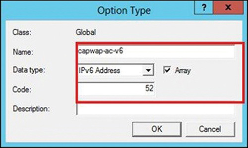
Now expand the scope that you want to use for your APs IPv6 assignment. Right-click Scope Options, and then select Configure Options. This is shown in Figure 2-38.

You can now choose the option 52 in the list of available options, and you can see it wears the name you gave it. In the New IPv6 Address field, enter the management IP of the primary WLC and click Add. You can then also add secondary and tertiary if you like. This is illustrated in Figure 2-39.

You can then verify this assignment on the AP itself (see Example 2-11; the output has been trimmed to show only the relevant lines for your understanding).
Example 2-11 Verification of the DHCPv6 Status of the AP
MyAP# show ipv6 dhcp interface

BVI1 is in client mode
Prefix State is IDLE
Address state is OPEN
Renew for address will be sent in 1d
List of known servers :
   Reachable via address: FE80::3E0E:24BB:FE2A:E123
   Configuration parameters:
      Address : 2001:1234:1234:1234:1234:1234::1/128
      Expires at Apr 11 2018 02:32 PM
   DNS server : 2001:1:2::1
   Domain name : ccie.com
   Capwap access controller : 2001:470:52C5:14::16
Capwap access controller : 2001:470:52C5:14::17
DNS
Domain Name System (DNS) is a name resolution method used to translate Internet domain names to IP addresses (but not necessarily only in that direction). DNS works on a hierarchy of domain levels. If we use the very famous Internet domains as an example, you have one (technically more, but still a very limited amount) root name server for the .com domain. That root server will be aware of cisco.com and will be able to return IP addresses tied to that domain. However, if I ask for the IP address of software.cisco.com, we start to picture that it’s not scalable for the root domain server to know all the subdomains and specific server IP addresses for all the domains under its authority. It can therefore redirect the request to the DNS server authoritative for the cisco.com subdomain. That one will definitely have the responsibility to know about software.cisco.com.
For the example, resolving this with the nslookup tool (present in all main laptops OS), the command line gives the following:
Nslookup software.cisco.com
Server :      <DNS server IP used by this laptop>

Software.cisco.com
Name: origin-software.cisco.com
Addresses: 2a02:a000:1:386:ac5
       23.218.189.151
Aliases : software.cisco.com
We can already picture how flexible this system is, because it allows you to return different IP addresses (v4 or v6) as well as name aliases. The whole domain name structure is also very scalable, because you could have server-name.department.continent.company.extension and can offload the administration of all the servers of that small team to the local continent-specific department of your company. Other parts of the company could manage their own DNS server responsible for their own subdomains without having to argue with you. It is important to note that what a DNS server returns to you will not necessarily be the same as what it will return to another requestor. A DNS server can very well give different replies to load-balance the load to several IP addresses or simply hand out a different IP mapping, depending where you are located on the globe.
There is also the concept of reverse DNS lookup, where you look up an IP address and the DNS server will let you know what name is linked to it, which can be practical in many situations.
There are several types of DNS records:
A (for Address) record: These are the “main” records and contain a host IPv4 address.
AAAA record: Contains a host of IPv6 addresses.
CNAME record: Allows you to redirect one name to another.
PTR: Points to a hostname (used therefore in reverse lookups).
MX record: Defines the mail server IP for the domain.
SRV record: Extension of the MX record for various services belonging to the domain (used by Active Directory to point to the domain controller and specific services in use for the domain).
NS record: Defines the DNS servers for the domain.
Cisco access points can discover the WLC using DNS. However, this also means that, before they can do so, the access points need to be configured with an IP address, know which domain they belong to, and know the DNS server IP address. This technically means that they need to obtain an IP address via DHCP. They will then try to resolve (as soon as they obtained their IP address and tested their gateway reachability) CISCO-CAPWAP-CONTROLLER.localdomain. The localdomain part will be replaced with the actual domain name, if you assigned one as part of the DHCP options. If there is an A-record for this in the local DNS server, the AP should receive the list of WLC IP addresses attached to it, and then try to join it.
SYSLOG
Syslog is a message logging system that started on UNIX but spread to most networking products because it is independent of the client and server types in use. The whole concept is about the syslog device sending messages (that don’t need any form of acknowledgement) to a server that will record all of them. Server software differs in the way they allow the administrator to browse and search through the mountain of logs received by all the devices using it as a syslog server, but the concept will remain the same. A syslog message is a combination of three things: severity level, facility (kind of like “syslog type”), and the actual message.
Facility clearly has a UNIX inspiration with types like kern, user, mail, auth, new, and so on. However there are eight custom facilities, local0, local1, all the way up to local7, which can be used for your own purposes. It’s then up to the network administrator to configure some devices to log to a given facility and other devices to other facilities.
Severities range from 0 to 7 and each one has guidelines for usage.
0. Emergency: Panic condition. Nearly never used apart from when a system might crash badly.
1. Alert: Major corruption requiring immediate action.
2. Critical: Critical errors (bad hardware, things going south real quick).
3. Error: This is the default logging level of many devices. It will log anything that is not a normal behavior.
4. Warning: Displays warning conditions that may not cause problems but shows possibly unexpected behavior.
5. Notice: Displays normal but significant conditions.
6. Informational: Informational messages.
7. Debug: Debug-level messages.
When you set the logging level to be 3 or Error, it means that the device will display all messages that are Error-level or more severe (so severity 2, 1, and 0 as well). Logging at debug level means that all severities of messages will be displayed and sent, and so on.
The Management > Logs > Config page is an easy go-to for syslog configuration on the controller. You can configure the IP of the syslog server the WLC will use for its logging, as well as the logging level (remember it will be that level and above) and the facility. In the Msg Log configuration section, you can choose the severity of logs to keep in the memory buffer (show msglog) and the severity that will be displayed on console session (that is disabled by default; historically, AireOS was not logging syslog to console). One trick is that this web page is only about the WLC syslogs. On the WLC command line you can also configure the syslog parameters for access points. It is best practice to configure syslog for your APs so that you can review their console output without having to plug an actual console cable to one whenever you suddenly have trouble with one (or more APs). Another way to achieve this is to return DHCP option 7 in the AP DHCP pool so that APs start to syslog their output as soon as they obtain network connectivity (which is helpful when you troubleshoot an AP not joining a WLC, and you don’t have console access to the AP).
While syslog messages and SNMP traps are two different things, there also are options to enable the sending of syslog messages when a given SNMP trap is sent. This section closes with a summary table of useful commands for syslog configuration and verification on the WLC and also on autonomous IOS APs (see Table 2-10), as well as a screenshot of a Kiwi Syslog server that received a couple of syslog message from APs and WLCs (see Figure 2-40).
Table 2-10 Summary of the Syslog-related Commands on the WLC
Command |
Purpose |
WLC> config logging syslog host <ip> |
Configures the IP address of the syslog server where WLC will send its log messages |
WLC> show msglog |
Will display all the buffered message logs sent and logged by the WLC (unless you choose a different severity for syslog level and for “buffered log level”) |
WLC> config ap syslog host global/<apname> <ip> |
Configures the syslog server for APs to directly syslog their messages to it |
WLC> config ap logging level <level> |
Configures the AP syslog logging level |
WLC> config ap logging facility <name> |
Configures the AP syslog facility |
aIOS(config)# logging host <server ip> |
Sets the IP address of syslog server on autonomous IOS APs |
aIOS(config)# logging facility <facility name> |
Sets the syslog facility on autonomous IOS APs |

NTP
Despite being more and more critical, Network Time Protocol (NTP) is still not heavily used by network administrators. NTP allows network devices to periodically resynchronize with a trusted time source and opens the doors to the amazing feeling of having the logs of all your network devices synchronized to the millisecond, allowing you to cross-check what happened during a particular event in the logs of multiple devices.
A very common NTP version is NTPv3 (and is the one used in the lab), but newer WLC software supports NTPv4. They are, however, all compatible with each other. The configuration is pretty straightforward on the WLC, in the web interface Controller page under the NTP > Server menu. You can add several NTP servers there, as well as configure the NTP polling interval. After your network device got the right time, it’s very unlikely that it needs to keep polling it frequently, so very long NTP polling intervals are fine. However, because network devices don’t use atomic ultra-high-precision clocks, it might start to slide a few seconds after weeks or months of uptime. Therefore, an NTP polling interval of a few hours is fine and ensures your device’s time is always as accurate as possible.
NTP also provides some form of authentication security with configurable keys.
While the inner workings of NTP are a bit beyond the scope of the CCIE exam, it is interesting to note that the NTP server will give the time in UTC format (without any time zone skew). It is thus acceptable to have an NTP server in another time zone. What about network latency then? Well, the NTP protocol also measures the network delay and adjusts the time received from the NTP server with the estimated delay it took the packet to arrive to the device, making sure the latency does not affect the time synchronization to a relevant extent. All that is pretty neat, but how do you set up an NTP server and how does a device decide which NTP is most reliable?
NTP uses the concept of stratum. A stratum-0 server is a reference clock and is not available on the network, but it will be connected to an NTP server that will be defined as a stratum-1 server (because it is one hop away from the reference clock). Any server that uses this stratum-1 server will be defined as a stratum-2 server, and so on. NTP only tolerates up to 16 stratum levels. If you set up one of your device as NTP server, its stratum will be S+1, S being the stratum of the reference NTP server used by your NTP server to get its time. If you decide to not have a reference server and set the time manually on your device, the stratum will be automatically set as 16. This is how NTP clients will know which server is the most reliable.
Configuring a router as NTP server is quite quick:
Router# config term
Router(config)# ntp master 4
Router(config)# ntp source Vlan1
Router(config)# interface Vlan1
Router(config-if)ntp broadcast
These commands will set the router to advertise its internal clock as a stratum 4 reference and will be a time server in VLAN1, using that SVI IP as source. Verifying all NTP details on the WLC is quite simple with the show time command (see Example 2-12).
Example 2-12 Example Output of NTP Details on a WLC
(Cisco Controller) >show timeTime.............................................
Wed May  9 13:39:47 2018Timezone delta................................... 0:0Timezone
  location................................NTP Servers    NTP Polling
  Interval.........................     3600     Index     NTP Key Index
  NTP Server                Status          NTP Msg Auth Status    -------  ----------
  ------------------------------------------------------------------------------------
  1              0                                192.168.1.11     In Sync
AUTH DISABLED(Cisco Controller) >
Let’s conclude with a summary of NTP-related commands on the WLC (see Table 2-11).
Table 2-11 NTP Configuration and Verification Commands on the WLC
Command |
Purpose |
WLC> show time |
Shows the current time and time zone as well as NTP settings and sync status |
WLC> config time ntp server <index> <ip> |
Configures a given IP address as NTP server (of index 1 to 3 if you want to have several sources) |
WLC> config time ntp interval <seconds> |
Configures the interval at which the WLC will resync its clock |
WLC> config time ntp key-auth add <key index> md5 ascii <key> |
Configures the NTP key (optional) |
WLC> config time ntp auth enable <server index> <key index> |
Configures authentication on NTP server index X by using the keys of key index Y |
Summary
This wraps up the infrastructure chapter of this book. As you can see, a CCIE Wireless does not need to know all the tiny details of those protocols. You can, however, expect that some of these protocols will appear as configuration tasks in the CCIE Wireless lab exam or will be required to bring the connectivity up. To declare yourself ready for the exam, all the knowledge of this chapter must be natural and common knowledge to you as you make sure the infrastructure network is ready before you configure anything wireless related. You can also expect this chapter to be a good source for troubleshooting actions, when you receive the preconfigured topology in the exam and some items were intentionally misconfigured (or simply missing sometimes) for you to troubleshoot. There is no point in trying to configure advanced wireless features (multicast or FlexConnect setups) if your infrastructure has dodgy VLAN configuration or suspicious multicast forwarding. Be sure to master this chapter before moving on to the next ones!