
CHAPTER 5
NETWORK AND TRANSPORT LAYERS
THE NETWORK layer and transport layer are responsible for moving messages from end to end in a network. They are so closely tied together that they are usually discussed together. The transport layer (layer 4) performs three functions: linking the application layer to the network, segmenting (breaking long messages into smaller packets for transmission), and session management (establishing an end-to-end connection between the sender and receiver). The network layer (layer 3) performs two functions: routing (determining the next computer to which the message should be sent to reach the final destination) and addressing (finding the address of that next computer). There are several standard transport and network layer protocols that specify how packets are to be organized, in the same way that there are standards for data link layer packets. However, only one protocol is in widespread use today: Transmission Control Protocol/Internet Protocol (TCP/IP), the protocol used on the Internet. This chapter takes a detailed look at how TCP/IP works.
OBJECTIVES ![]()
- Be aware of the TCP/IP protocols
- Be familiar with linking to the application layer, segmenting, and session management
- Be familiar with addressing
- Be familiar with routing
- Understand how TCP/IP works
CHAPTER OUTLINE ![]()
5.2 TRANSPORT AND NETWORK LAYER PROTOCOLS
5.2.1 Transmission Control Protocol (TCP)
5.3.1 Linking to the Application Layer
5.6.1 Known Addresses, Same Subnet
5.6.2 Known Addresses, Different Subnet
5.6.5 TCP/IP and Network Layers
5.7 IMPLICATIONS FOR MANAGEMENT
5.1 INTRODUCTION
The transport and network layers are so closely tied together that they are almost always discussed together. For this reason, we discuss them in the same chapter. TCP/IP is the most commonly used set of transport and network layer protocols, so this chapter focuses exclusively on TCP/IP.
The transport layer links the application software in the application layer with the network and is responsible for the end-to-end delivery of the message. The transport layer accepts outgoing messages from the application layer (e.g., Web, email, and so on, as described in Chapter 2) and segments them for transmission. Figure 5.1 shows the application layer software producing an SMTP packet that is split into two smaller TCP segments by the transport layer. The Protocol Data Unit (PDU) at the transport layer is called a segment. The network layer takes the messages from the transport layer and routes them through the network by selecting the best path from computer to computer through the network (and adds an IP packet). The data link layer adds an Ethernet frame and instructs the physical layer hardware when to transmit. As we saw in Chapter 1, each layer in the network has its own set of protocols that are used to hold the data generated by higher layers, much like a set of matryoshka (nested Russian dolls).

FIGURE 5.1 Message transmission using layers. HTTP = Hypertext Transfer Protocol; IP = Internet Protocol; TCP = Transmission Control Protocol
The network and transport layers also accept incoming messages from the data link layer and organize them into coherent messages that are passed to the application layer. For example, as in Figure 5.1 a large email message might require several data link layer frames to transmit. The transport layer at the sender would break the message into several smaller segments and give them to the network layer to route, which in turn gives them to the data link layer to transmit. The network layer at the receiver would receive the individual packets from the data link layer, process them, and pass them to the transport layer, which would reassemble them into the one email message before giving it to the application layer.
In this chapter, we provide a brief look at the transport and network layer protocols, before turning our attention to how TCP/IP works. We first examine the transport layer functions. Addressing and routing are performed by the transport layer and network layers working together, so we will discuss them together rather than separate them according to which part is performed by the transport layer and which by the network layer.
5.2 TRANSPORT AND NETWORK LAYER PROTOCOLS
There are different transport/network layer protocols, but one family of protocols, TCP/IP, dominates. Each transport and network layer protocol performs essentially the same functions, but each is incompatible with the others unless there is a special device to translate between them. In this chapter, we focus only on TCP/IP. A good overview of protocols, at all layers, is available at: www.protocols.com.
The Transmission Control Protocol/Internet Protocol (TCP/IP) was developed for the U.S. Department of Defense's Advanced Research Project Agency network (ARPANET) by Vinton Cerf and Bob Kahn in 1974. TCP/IP is the transport/network layer protocol used on the Internet. It is the world's most popular protocol set, used by almost all BNs and WANs. TCP/IP allows reasonably efficient and error-free transmission. Because it performs error checking, it can send large files across sometimes unreliable networks with great assurance that the data will arrive uncorrupted. TCP/IP is compatible with a variety of data link protocols, which is one reason for its popularity.
As the name implies, TCP/IP has two parts. TCP is the transport layer protocol that links the application layer to the network layer. It performs segmenting: breaking the data into smaller PDUs called segments, numbering them, ensuring each segment is reliably delivered, and putting them in the proper order at the destination. IP is the network layer protocol and performs addressing and routing. IP software is used at each of the intervening computers through which the message passes; it is IP that routes the message to the final destination. The TCP software needs to be active only at the sender and the receiver, because TCP is involved only when data comes from or goes to the application layer.

FIGURE 5.2 Transmission Control Protocol (TCP) segment, ACK = acknowledgment; CRC = cyclical redundancy check
5.2.1 Transmission Control Protocol (TCP)
A typical TCP segment has 192-bit header (24 bytes) of control information (Figure 5.2). Among other fields, it contains the source and destination port identifier. The destination port tells the TCP software at the destination to which application layer program the application layer packet should be sent, whereas the source port tells the receiver which application layer program the packet is from. The TCP segment also provides a sequence number so that the TCP software at the destination can assemble the segments into the correct order and make sure that no segments have been lost.
The options field is optional, so in many cases it is omitted. In this case, TCP has a length of 20 bytes (160 bits). The header length field is used to tell the receiver how long the TCP packet is—that is, whether the options field is included or not.
TCP/IP has a second type of transport layer protocol called User Datagram Protocol (UDP). UDP PDUs are called datagrams. Typically, UDP is used when the sender needs to send a single small packet to the receiver (e.g., for a DNS request, which we discuss later in this chapter). When there is only one small packet to be sent, the transport layer doesn't need to worry about segmenting the outgoing messages or reassembling them upon receipt, so transmission can be faster. A UDP datagram has only four fields (eight bytes of overhead) plus the application layer packet: source port, destination port, length, and a CRC-16. Unlike TCP, UDP does not check for lost messages, so occasionally a UDP datagram is lost, and the message must be resent. Interestingly, it is not the transport layer that decides whether TCP or UDP is going to be used. This decision is left to the engineer that is writing the application.
5.2.2 Internet Protocol (IP)
The Internet Protocol (IP) is the network layer protocol. Network layer PDUs are called packets. Two forms of IP are currently in use. The older form is IP version 4 (IPv4), which also has a 192-bit header (24 bytes) (Figure 5.3). This header contains source and destination addresses, packet length, and packet number.
IP version 4 is being replaced by IPv6, which has a 320-bit header (40 bytes) (Figure 5.4). The primary reason for the increase in the packet size is an increase in the address size from 32 bits to 128 bits. IPv6’s simpler packet structure makes it easier to perform routing and supports a variety of new approaches to addressing and routing.
Development of the IPv6 came about because IP addresses were being depleted on the Internet. IPv4 has a four-byte address field, which means there is a theoretical maximum of about 4.2 billion addresses. However, about 500 million of these addresses are reserved and cannot be used, and the way addresses were assigned in the early days of the Internet means that a small number of companies received several million addresses, even when they didn't need all of them. With the increased growth in Internet users, and the explosion in mobile Internet devices, current estimates project that we will run out of IPv4 addresses somewhere in 2011.

FIGURE 5.3 Internet Protocol (IP) packet (version 4). CRC = cyclical redundancy check

FIGURE 5.4 Internet Protocol (IP) packet (version 6)
Internet Protocol version 6 uses a 16-byte long address which provides a theoretical maximum of 3.4 × 1038 addresses—more than enough for the foreseeable future. IPv4 uses decimals to express addresses (e.g., 128.192.55.72), but IPv6 uses hexadecimal (base 16) like Ethernet to express addresses, which makes it slightly more confusing to use. Addresses are eight sets of 2-byte numbers (e.g., 2001:0890:0600: 00d1:0000:0000:abcd:f010), but because this can be long to write, there is a IPv6 “com-pressed notation” that eliminates the leading zeros within each block and blocks that are all zeros. So the IPv6 address above could also be written as 2001:890:600:d1::abcd:f010.
Adoption of IPv6 has been slow. Most organizations have not felt the need to change because IPv6 provides few benefits other than the larger address space and requires their staff to learn a whole new protocol. In most cases, the shortage of addresses on the Internet doesn't affect organizations that already have Internet addresses, so there is little incentive to convert to IPv6. Most organizations that implement IPv6 also run IPv4, and IPv6 is not backward-compatible with IPv4, which means that all network devices must be changed to understand both IPv4 and IPv6. The cost of this conversion, along with the few benefits it provides to organizations that do convert, has led a number of commentators to refer to this as the IPv6 “mess.” In order to encourage the move to IPv6, the U.S. government required all of its agencies to convert to IPv6 on their WANs and backbone networks by June 2008, but the change was not completed on time.
The size of the message field depends on the data link layer protocol used. TCP/IP is commonly combined with Ethernet. Ethernet has a maximum packet size of 1,492 bytes, so the maximum size of a TCP message field if IPv4 is used is 1,492 − 24 (the size of the TCP header) − 24 (the size of the IPv4 header) = 1,444.
5.3 TRANSPORT LAYER FUNCTIONS
The transport layer links the application software in the application layer with the network and is responsible for segmenting large messages into smaller ones for transmission and for managing the session (the end-to-end delivery of the message). One of the first issues facing the application layer is to find the numeric network address of the destination computer. Different protocols use different methods to find this address. Depending on the protocol—and which expert you ask—finding the destination address can be classified as a transport layer function, a network layer function, a data link layer function, or an application layer function with help from the operating system. In all honesty, understanding how the process works is more important than memorizing how it is classified. The next section discusses addressing at the network layer and transport layer. In this section, we focus on three unique functions performed by the transport layer: linking the application layer to the network layer, segmenting, and session management.
MANAGEMENT FOCUS
The address space of IPv4 is running out very quickly. Approximately 1.66 million IPv4 addresses were assigned every day in 2010 and the prediction was that by early March 2011 we would run out of IPv4 address space. However, as we are making the final edits to this book in April, there are still about two hundred thousand IPv4 addresses left. One can even continuously monitor the decreasing number of IPv4 addresses on twitter (@IPv4Countdown).
Rather than slowly moving to IPv6 and learning a new address system, the shortage of IPv4 addresses was overcome by NAT (Network Address Translation) that translates private non-routable addresses to a routable IPv4 address. However, NAT might delay the real need to deal with the shortage of IPv4 address space by only about 1 year. Thus, we are counting down to the inevitable collapse of IPv4, also referred to as ‘IPcalypse’ by the supporters of IPv6.
_________
5.3.1 Linking to the Application Layer
Most computers have many application layer software packages running at the same time. Users often have Web browsers, email programs, and word processors in use at the same time on their client computers. Likewise, many servers act as Web servers, mail servers, FTP servers, and so on. When the transport layer receives an incoming message, the transport layer must decide to which application program it should be delivered. It makes no sense to send a Web page request to email server software.
With TCP/IP, each application layer software package has a unique port address. Any message sent to a computer must tell TCP (the transport layer software) the application layer port address that is to receive the message. Therefore, when an application layer program generates an outgoing message, it tells the TCP software its own port address (i.e., the source port address) and the port address at the destination computer (i.e., the destination port address). These two port addresses are placed in the first two fields in the TCP segment (see Figure 5.2).
Port addresses can be any 16-bit (2-byte) number. So how does a client computer sending a Web request to a Web server know what port address to use for the Web server? Simple. On the Internet, all port addresses for popular services such as the Web, email, and FTP have been standardized. Anyone using a Web server should set up the Web server with a port address of 80 and is called the well-known port. Web browsers, therefore, automatically generate a port address of 80 for any Web page you click on. FTP servers use port 21, Telnet 23, SMTP 25, and so on. Network managers are free to use whatever port addresses they want, but if they use a nonstandard port number, then the application layer software on the client must specify the correct port number.1

FIGURE 5.5 Linking to application layer services
Figure 5.5 shows a user running three applications on the client (Internet Explorer, Outlook, and RealPlayer), each of which has been assigned a different port number, called temporary port number (1027, 1028, and 7070, respectively). Each of these can simultaneously send and receive data to and from different servers and different applications on the same server. In this case, we see a message sent by Internet Explorer on the client (port 1027) to the Web server software on the xyz.com server (port 80). We also see a message sent by the mail server software on port 25 to the email client on port 1028. At the same time, the RealPlayer software on the client is sending a request to the music server software (port 554) at 123.com.
5.3.2 Segmenting
Some messages or blocks of application data are small enough that they can be transmitted in one frame at the data link layer. However, in other cases, the application data in one “message” is too large and must be broken into several frames (e.g., Web pages, graphic images). As far as the application layer is concerned, the message should be transmitted and received as one large block of data. However, the data link layer can transmit only messages of certain lengths. It is therefore up to the sender's transport layer to break the data into several smaller segments that can be sent by the data link layer across the circuit. At the other end, the receiver's transport layer must receive all these separate segments and recombine them into one large message.
Segmenting means to take one outgoing message from the application layer and break it into a set of smaller segments for transmission through the network. It also means to take the incoming set of smaller segments from the network layer and reassemble them into one message for the application layer. Depending on what the application layer software chooses, the incoming packets can either be delivered one at a time or held until all packets have arrived and the message is complete. Web browsers, for example, usually request delivery of packets as they arrive, which is why your screen gradually builds a piece at a time. Most email software, on the other hand, usually requests that messages be delivered only after all packets have arrived and TCP has organized them into one intact message, which is why you usually don't see email messages building screen by screen.
The TCP is also responsible for ensuring that the receiver has actually received all segments that have been sent. TCP therefore uses continuous ARQ (see Chapter 4).
One of the challenges at the transport layer is deciding how big to make the segments. Remember, we discussed packet sizes in Chapter 4. When transport layer software is set up, it is told what size segments it should use to make best use of its own data link layer protocols (or it chooses the default size of 536). However, it has no idea what size is best for the destination. Therefore, the transport layer at the sender negotiates with the transport layer at the receiver to settle on the best segment sizes to use. This negotiation is done by establishing a TCP connection between the sender and receiver.
5.3.3 Session Management
A session can be thought of as a conversation between two computers. When the sending computer wants to send a message to the receiver, it usually starts by establishing a session with that computer. The sender transmits the segments in sequence until the conversation is done, and then the sender ends the session. This approach to session management is called connection-oriented messaging.
Sometimes, the sender only wants to send one short information message or a request. In this case, the sender may choose not to start a session, but just send the one quick message and move on. This approach is called connectionless messaging.
Connection-Oriented Messaging Connection-oriented messaging sets up a TCP connection (also called a session) between the sender and receiver. To establish a connection, the transport layer on both the sender and the receiver must send a SYN (synchronize) and receive a ACK (acknowledgement) segment. This process starts with the sender (usually a client) sending a SYN to the receiver (usually a server). The server responds with an ACK for the sender's/client's SYN and then sends its own SYN. SYN is usually a randomly generated number that identifies a packet. The last step is when the client sends an ACK for the server's SYN. This is called the three-way handshake and this process also contains the segment size negotiation.
Once the connection is established, the segments flow between the sender and receiver. TCP uses the continuous ARQ (sliding window) technique described in Chapter 4 to make sure that all segments arrive and to provide flow control.
When the transmission is complete, the session is terminated using a four-way handshake. Because TCP/IP connection is a full-duplex connection, each side of the session has to terminate the connection independently. The sender (i.e., the client) will start by sending with a FIN to inform the receiver (i.e., the server) that is finished sending data. The server acknowledges the FIN sending an ACK. Then the server sends a FIN to the client. The connection is successfully terminated when the server receives the ACK for its FIN.
Connectionless Messaging Connectionless messaging means each packet is treated separately and makes its own way through the network. Unlike connection-oriented routing, no connection is established. The sender simply sends the packets as separate, unrelated entities, and it is possible that different packets will take different routes through the network, depending on the type of routing used and the amount of traffic. Because packets following different routes may travel at different speeds, they may arrive out of sequence at their destination. The sender's network layer, therefore, puts a sequence number on each packet, in addition to information about the message stream to which the packet belongs. The network layer must reassemble them in the correct order before passing the message to the application layer.
Transmission Control Protocol/Internet Protocol can operate either as connection-oriented or connectionless. When connection-oriented messaging is desired, TCP is used. When connectionless messaging is desired, the TCP segment is replaced with a User Datagram Protocol (UDP) packet. The UDP packet is much smaller than the TCP packet (only 8 bytes).
Connectionless is most commonly used when the application data or message can fit into one single message. One might expect, for example, that because HTTP requests are often very short, they might use UDP connectionless rather than TCP connection-oriented messaging. However, HTTP always uses TCP. All of the application layer software we have discussed so far uses TCP (HTTP, SMTP, FTP, Telnet). UDP is most commonly used for control messages such as addressing (DHCP [Dynamic Host Configuration Protocol], discussed later in this chapter), routing control messages (RIP [Routing Information Protocol], discussed later in this chapter), and network management (SNMP [Simple Network Management Protocol], discussed in Chapter 12).
Quality of Service Quality of Service (QoS) routing is a special type of connection-oriented messaging in which different connections are assigned different priorities. For example, videoconferencing requires fast delivery of packets to ensure that the images and voices appear smooth and continuous; they are very time dependent because delays in routing seriously affect the quality of the service provided. Email packets, on the other hand, have no such requirements. Although everyone would like to receive email as fast as possible, a 10-second delay in transmitting an email message does not have the same consequences as a 10-second delay in a videoconferencing packet.
With QoS routing, different classes of service are defined, each with different priorities. For example, a packet of videoconferencing images would likely get higher priority than would an SMTP packet with an email message and thus be routed first. When the transport layer software attempts to establish a connection (i.e., a session), it specifies the class of service that connection requires. Each path through the network is designed to support a different number and mix of service classes. When a connection is established, the network ensures that no connections are established that exceed the maximum number of that class on a given circuit.
QoS routing is common in certain types of networks (e.g., ATM, as discussed in Chapter 8). The Internet provides several QoS protocols that can work in a TCP/IP environment. Resource Reservation Protocol (RSVP) and Real-Time Streaming Protocol (RTSP) both permit application layer software to request connections that have certain minimum data transfer capabilities. As one might expect, RTSP is geared toward audio/video streaming applications while RSVP is more general purpose.
Both QoS protocols, RSVP and RTSP, are used to create a connection (or session) and request a certain minimum guaranteed data rate. Once the connection has been established, they use Real-Time Transport Protocol (RTP) to send packets across the connection. RTP contains information about the sending application, a packet sequence number, and a time stamp so that the data in the RTP packet can be synchronized with other RTP packets by the application layer software if needed.
With a name like Real-Time Transport Protocol, one would expect RTP to replace TCP and UDP at the transport layer. It does not. Instead, RTP is combined with UDP. (If you read the previous paragraph carefully, you noticed that RTP does not provide source and destination port addresses.) This means that each real-time packet is first created using RTP and then surrounded by a UDP datagram, before being handed to the IP software at the network layer.
5.4 ADDRESSING
Before you can send a message, you must know the destination address. It is extremely important to understand that each computer has several addresses, each used by a different layer. One address is used by the data link layer, another by the network layer, and still another by the application layer.
When users work with application software, they typically use the application layer address. For example, in Chapter 2, we discussed application software that used Internet addresses (e.g., www.indiana.edu). This is an application layer address (or a server name). When a user types an Internet address into a Web browser, the request is passed to the network layer as part of an application layer packet formatted using the HTTP protocol (Figure 5.6) (see Chapter 2).
The network layer software, in turn, uses a network layer address. The network layer protocol used on the Internet is IP, so this Web address (www.indiana.edu) is translated into an IP address that is 4 bytes long when using IPv4 (e.g., 129.79.127.4) (Figure 5.6). This process is similar to using a phone book to go from someone's name to his or her phone number.2
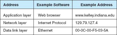
The network layer then determines the best route through the network to the final destination. On the basis of this routing, the network layer identifies the data link layer address of the next computer to which the message should be sent. If the data link layer is running Ethernet, then the network layer IP address would be translated into an Ethernet address. Chapter 3 shows that Ethernet addresses are 6 bytes in length, so a possible address might be 00-0F-00-81-14-00 (Ethernet addresses are usually expressed in hexadecimal) (Figure 5.6). Data link layer addresses are needed only on multipoint circuits which have more than one computer on them. For example, many WANs are built with point-to-point circuits that use PPP as the data link layer protocol. These networks do not have data link layer addresses.
5.4.1 Assigning Addresses
In general, the data link layer address is permanently encoded in each network card, which is why the data link layer address is also commonly called the physical address or the MAC address. This address is part of the hardware (e.g., Ethernet card) and can never be changed. Hardware manufacturers have an agreement that assigns each manufacturer a unique set of permitted addresses, so even if you buy hardware from different companies, they will never have the same address. Whenever you install a network card into a computer, it immediately has its own data link layer address that uniquely identifies it from every other computer in the world.
Network layer addresses are generally assigned by software. Every network layer software package usually has a configuration file that specifies the network layer address for that computer. Network managers can assign any network layer addresses they want. It is important to ensure that every computer on the same network has a unique network layer address so that every network has a standards group that defines what network layer addresses can be used by each organization.
Application layer addresses (or server names) are also assigned by a software configuration file. Virtually all servers have an application layer address, but most client computers do not. This is because it is important for users to easily access servers and the information they contain, but there is usually little need for someone to access someone else's client computer. As with network layer addresses, network managers can assign any application layer address they want, but a network standards group must approve application layer addresses to ensure that no two computers have the same application layer address. Network layer addresses and application layer addresses go hand in hand, so the same standards group usually assigns both (e.g., www.indiana.edu at the application layer means 129.79.78.4 at the network layer). It is possible to have several application layer addresses for the same computer. For example, one of the Web servers in the Kelley School of Business at Indiana University is called both www.kelley.indiana.edu and www.kelley.iu.edu.
Internet Addresses No one is permitted to operate a computer on the Internet unless they use approved addresses. ICANN (Internet Corporation for Assigned Names and Numbers) is responsible for managing the assignment of network layer addresses (i.e., IP addresses) and application layer addresses (e.g., www.indiana.edu). ICANN sets the rules by which new domain names (e.g.,.com,.org,.ca,.uk) are created and IP address numbers are assigned to users. ICANN also directly manages a set of Internet domains (e.g.,.com,.org,.net) and authorizes private companies to become domain name registrars for those domains. Once authorized, a registrar can approve requests for application layer addresses and assign IP numbers for those requests. This means that individuals and organizations wishing to register an Internet name can use any authorized registrar for the domain they choose, and different registrars are permitted to charge different fees for their registration services. Many registrars are authorized to issue names and addresses in the ICANN managed domains, as well as domains in other countries (e.g.,.ca,.uk,.au).
Several application layer addresses and network layer addresses can be assigned at the same time. IP addresses are often assigned in groups, so that one organization receives a set of numerically similar addresses for use on its computers. For example, Indiana University has been assigned the set of application layer addresses that end in indiana.edu and iu.edu and the set of IP addresses in the 129.79.x.x range (i.e., all IP addresses that start with the numbers 129.79).
In the old days of the Internet, addresses used to be assigned by class. A class A address was one for which the organization received a fixed first byte and could allocate the remaining three bytes. For example, Hewlett-Packard (HP) was assigned the 15.x.x.x address range, which has about 16 million addresses. A class B address has the first two bytes fixed, and the organization can assign the remaining two bytes. Indiana University has a class B address, which provides about 65,000 addresses. A class C address has the first three bytes fixed with the organization able to assign the last byte, which provides about 250 addresses.
People still talk about Internet address classes, but addresses are no longer assigned in this way and most network vendors are no longer using the terminology. The newer terminology is classless addressing in which a slash is used to indicate the address range (it's also called slash notation). For example, 128.192.1.0/24 means the first 24 bits (3 bytes) are fixed, and the organization can allocate the last byte (8 bits).
One of the problems with the current address system is that the Internet is quickly running out of addresses. Although the 4-byte address of IPv4 provides more than 4 billion possible addresses, the fact that they are assigned in sets significantly limits the number of usable addresses. For example, the address range owned by Indiana University includes about 65,000 addresses, but the university will probably not use all of them.
The IP address shortage was one of the reasons behind the development of IPv6, discussed previously. Once IPv6 is in wide use, the current Internet address system will be replaced by a totally new system based on 16-byte addresses. Most experts expect that all the current 4-byte addresses will simply be assigned an arbitrary 12-byte prefix (e.g., all zeros) so that the holders of the current addresses can continue to use them.
Subnets Each organization must assign the IP addresses it has received to specific computers on its networks. To make the IP address assignment more functional, we use an addressing hierarchy. The first part of the address defines the network, and the second part of the address defines a particular computer or host on the network. However, it is not efficient to assign every computer to the same network. Rather, subnetworks or subnets are designed on the network that subdivide the network into logical pieces. For example, suppose a university has just received a set of addresses starting with 128.192.x.x. It is customary to assign all the computers in the same LAN numbers that start with the same first three digits, so the business school LAN might be assigned 128.192.56.x, which means all the computers in that LAN would have IP numbers starting with those numbers (e.g., 128.192.56.4, 128.192.56.5, and so on) (Figure 5.7). The subnet ID for this LAN than is 128.192.56. Two addresses on this subnet cannot be assigned as IP address to any computer. The first address is 128.192.56.0 and this is the network address. The second address is 128.192.56.255 is the broadcast address. The computer science LAN might be assigned 128.192.55.x, and likewise, all the other LANs at the university and the BN that connects them would have a different set of numbers. Similar to the business school LAN, the computer science LAN would have a subnet ID 128.192.55. Thus, 128.192.55.0 and 128.192.55.255 cannot be assigned to any computer on this network because they are reserved for the network address and broadcast address.

Routers connect two or more subnets so they have a separate address on each subnet. Without routers, the two subnets would not be able to communicate. The routers in Figure 5.7, for example, have two addresses each because they connect two subnets and must have one address in each subnet.
Although it is customary to use the first 3 bytes of the IP address to indicate different subnets, it is not required. Any portion of the IP address can be designated as a subnet by using a subnet mask. Every computer in a TCP/IP network is given a subnet mask to enable it to determine which computers are on the same subnet (i.e., LAN) that it is on and which computers are outside of its subnet. Knowing whether a computer is on your subnet is very important for message routing, as we shall see later in this chapter.
For example, a network could be configured so that the first two bytes indicated a subnet (e.g., 128.184.x.x), so all computers would be given a subnet mask giving the first two bytes as the subnet indicator. This would mean that a computer with an IP address of 128.184.22.33 would be on the same subnet as 128.184.78.90.
IP addresses are binary numbers, so partial bytes can also be used as subnets. For example, we could create a subnet that has IP addresses between 128.184.55.1 and 128.184.55.127, and another subnet with addresses between 128.184.55.128 and 128.184.55.254.
Dynamic Addressing To this point, we have said that every computer knows its network layer address from a configuration file that is installed when the computer is first attached to the network. However, this leads to a major network management problem. Any time a computer is moved or its network is assigned a new address, the software on each individual computer must be updated. This is not difficult, but it is very time consuming because someone must go from office to office, editing files on each individual computer.
The easiest way around this is dynamic addressing. With this approach, a server is designated to supply a network layer address to a computer each time the computer connects to the network. This is commonly done for client computers but usually not done for servers.
The most common standard for dynamic addressing is Dynamic Host Configuration Protocol (DHCP). DHCP does not provide a network layer address in a configuration file. Instead, there is a special software package installed on the client that instructs it to contact a DHCP server to obtain an address. In this case, when the computer is turned on and connects to the network, it first issues a broadcast DHCP message that is directed to any DHCP server that can “hear” the message. This message asks the server to assign the requesting computer a unique network layer address. The server runs a corresponding DHCP software package that responds to these requests and sends a message back to the client, giving it its network layer address (and its subnet mask).
The DHCP server can be configured to assign the same network layer address to the computer (on the basis of its data link layer address) each time it requests an address, or it can lease the address to the computer by picking the “next available” network layer address from a list of authorized addresses. Addresses can be leased for as long as the computer is connected to the network or for a specified time limit (e.g., 2 hours). When the lease expires, the client computer must contact the DHCP server to get a new address. Address leasing is commonly used by ISPs for dial-up users. ISPs have many more authorized users than they have authorized network layer addresses because not all users can log in at the same time. When a user logs in, his or her computer is assigned a temporary TCP/IP address that is reassigned to the next user when the first user hangs up.
TECHNICAL FOCUS
Subnet masks tell computers what part of an Internet Protocol (IP) address is to be used to determine whether a destination is on the same subnet or on a different subnet. A subnet mask is a 4-byte binary number that has the same format as an IP address and is not routable on the network. A 1 in the subnet mask indicates that that position is used to indicate the subnet. A zero indicates that it is not. Therefore, a mask can only contain a continuous stream of ones.
A subnet mask of 255.255.255.0 means that the first three bytes indicate the subnet; all computers with the same first three bytes in their IP addresses are on the same subnet. This is because 255 expressed in binary is 11111111.
In contrast, a subnet mask of 255.255.0.0 indicates that the first two bytes refer to the same subnet.
Things get more complicated when we use partial-byte subnet masks. For example, suppose the subnet mask was 255.255.255.128. In binary numbers, this is expressed as:
11111111.11111111.11111111.10000000
This means that the first three bytes plus the first bit in the fourth byte indicate the subnet address.
Likewise, a subnet mask of 255.255.254.0 would indicate the first two bytes plus the first seven bits of third byte indicate the subnet address, because in binary numbers, this is:
11111111.11111111.11111110.00000000
The bits that are ones are called network bits because they indicate which part of an address is the network or subnet part, whereas the bits that are zeros are called host bits because they indicate which part is unique to a specific computer or host.
Dynamic addressing greatly simplifies network management in non-dial-up networks, too. With dynamic addressing, address changes need to be made only to the DHCP server, not to each individual computer. The next time each computer connects to the network or whenever the address lease expires, the computer automatically gets the new address.
5.4.2 Address Resolution
To send a message, the sender must be able to translate the application layer address (or server name) of the destination into a network layer address and in turn translate that into a data link layer address. This process is called address resolution. There are many different approaches to address resolution that range from completely decentralized (each computer is responsible for knowing all addresses) to completely centralized (there is one computer that knows all addresses). TCP/IP uses two different approaches, one for resolving application layer addresses into IP addresses and a different one for resolving IP addresses into data link layer addresses.
Server Name Resolution Server name resolution is the translation of application layer addresses into network layer addresses (e.g., translating an Internet address such as www.yahoo.com into an IP address such as 204.71.200.74). This is done using the Domain Name Service (DNS). Throughout the Internet a series of computers called name servers provides DNS services. These name servers have address databases that store thousands of Internet addresses and their corresponding IP addresses. These name servers are, in effect, the “directory assistance” computers for the Internet. Anytime a computer does not know the IP number for a computer, it sends a message to the name server requesting the IP number. There are about a dozen high-level name servers that provide IP addresses for most of the Internet, with thousands of others that provide IP addresses for specific domains.
Whenever you register an Internet application layer address, you must inform the registrar of the IP address of the name server that will provide DNS information for all addresses in that name range. For example, because Indiana University owns the indiana.edu name, it can create any name it wants that ends in that suffix (e.g., www.indiana.edu, www.kelley.indiana.edu, abc.indiana.edu). When it registers its name, it must also provide the IP address of the DNS server that it will use to provide the IP addresses for all the computers within this domain name range (i.e., everything ending in. indiana.edu). Every organization that has many servers also has its own DNS server, but smaller organizations that have only one or two servers often use a DNS server provided by their ISP. DNS servers are maintained by network managers, who update their address information as the network changes. DNS servers can also exchange information about new and changed addresses among themselves, a process called replication.
When a computer needs to translate an application layer address into an IP address, it sends a special DNS request packet to its DNS server.3 This packet asks the DNS server to send to the requesting computer the IP address that matches the Internet application layer address provided. If the DNS server has a matching name in its database, it sends back a special DNS response packet with the correct IP address. If that DNS server does not have that Internet address in its database, it will issue the same request to another DNS server elsewhere on the Internet.4
For example, if someone at the University of Toronto asked for a Web page on the server (www.kelley.indiana.edu) at Indiana University, the software on the Toronto client computer would issue a DNS request to the University of Toronto DNS server (Figure 5.8). This DNS server probably would not know the IP address of our server, so it would forward the request to the DNS root server that it knows stores addresses for the.edu domain. The.edu root server probably would not know Indiana University's server's IP address either, but it would know that the DNS server on the campus could supply the address. So it would forward the request to the Indiana University DNS server, which would reply to the.edu server with a DNS response containing the requested IP address. The.edu server in turn would send that response to the DNS server at the University of Toronto, which in turn would send it to the computer that requested the address.
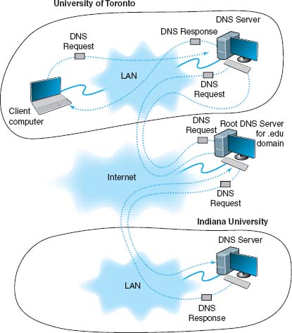
FIGURE 5.8 How the DNS system works
This is why it sometimes takes longer to access certain sites. Most DNS servers know only the names and IP addresses for the computers in their part of the network. Some store frequently used addresses (e.g., www.yahoo.com). If you try to access a computer that is far away, it may take a while before your computer receives a response from a DNS server that knows the IP address.
Once your application layer software receives an IP address, it is stored on your computer in a DNS cache. This way, if you ever need to access the same computer again, your computer does not need to contact a DNS server. The DNS cache is routinely deleted whenever you turn off your computer.
Data Link Layer Address Resolution To actually send a message on a multipoint circuit, the network layer software must know the data link layer address of the receiving computer. The final destination may be far away (e.g., sending from Toronto to Indiana). In this case, the network layer would route the message by selecting a path through the network that would ultimately lead to the destination. (Routing is discussed in the next section.) The first step on this route would be to send the message to its router.
To send a message to another computer in its subnet, a computer must know the correct data link layer address. In this case, the TCP/IP software sends a broadcast message to all computers in its subnet. A broadcast message, as the name suggests, is received and processed by all computers in the same LAN (which is usually designed to match the IP subnet). The message is a specially formatted request using Address Resolution Protocol (ARP) that says, “Whoever is IP address xxx.xxx.xxx.xxx, please send me your data link layer address.” The software in the computer with that IP address then sends an ARP response with its data link layer address. The sender transmits its message using that data link layer address. The sender also stores the data link layer address in its address table for future use.5
5.5 ROUTING
Routing is the process of determining the route or path through the network that a message will travel from the sending computer to the receiving computer. In some networks (e.g., the Internet), there are many possible routes from one computer to another. In other networks (e.g., internal company networks), there may only be one logical route from one computer to another.6 In either case, some device has to route messages through the network.
Routing is done by special devices called routers. Routers are usually found at the edge of subnets because they are the devices that connect subnets together and enable messages to flow from one subnet to another as the messages move through the network from sender to receiver. Figure 5.9 shows a small network with two routers, R1 and R2. This network has five subnets, plus a connection to the Internet. Each subnet has its own range of addresses (e.g., 10.10.51.x), and each router has its IP address (e.g., 10.10.1.1). The first router (R1) has four connections, one to the Internet, one to router R2 and one to each of two subnets. Each connection, called an interface, is numbered from 0 to 3. The second router (R2) has also has four interfaces, one that connects to R1 and three that connect to other subnets.
Every router has a routing table that specifies how messages will travel through the network. In its simplest form, the routing table is a two-column table. The first column lists every network or computer that the router knows about and the second column lists the interface that connects to it. Figure 5.10 shows the routing tables that might be used by routers in Figure 5.9. The first entry in R1’s routing table says that any message with an IP address in the range from 10.10.51.0 to 10.10.51.255 should be sent out on interface 1.
A router uses its routing table to decide where to send the messages it receives. Suppose a computer in the 10.10.43.x subnet sends an HTTP request for a Web page that is located on the company's Web server, which is in the 10.10.20.x subnet (let's say the Web server has an IP address of 10.10.20.10). The computer would send the message to its router, R2. R2 would look at the IP address on the IP packet and search its routing table for a matching address. It would search through the table, from top to bottom, until it reached the third entry, which is a range of addresses that contains the Web server's address (10.10.20.10). The matching interface is number 2, so R2 would transmit the message on this interface.
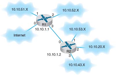
FIGURE 5.9 A small corporate network
The process is similar if the same computer requested a page somewhere on the Internet (e.g., www.yahoo.com). The computer would send the message to its router, R2. R2 would look at the IP address on the IP packet (www.yahoo.com has an IP address of 69.147.125.65) and search its routing table for a matching entry. It would look at the first four entries and not find a match. It reaches the final entry that says to send a message with any other address on interface 0, so R2 would transmit this message on interface 0 to router R1.
The same process would be performed by R1. It would search through its routing table for an address that matched 69.147.125.65 and not find it. When it reaches the final entry, R1 knows to send this message on interface 0 into the Internet.

FIGURE 5.10 Sample routing tables
5.5.1 Types of Routing
There are three fundamental approaches to routing: centralized routing, static routing, and dynamic routing. As you will see in the TCP/IP Example section later in this chapter, the Internet uses all three approaches.
Centralized Routing With centralized routing, all routing decisions are made by one central computer or router. Centralized routing is commonly used in host-based networks (see Chapter 2), and in this case, routing decisions are rather simple. All computers are connected to the central computer, so any message that needs to be routed is simply sent to the central computer, which in turn retransmits the message on the appropriate circuit to the destination.
Static Routing Static routing is decentralized, which means that all computers or routers in the network make their own routing decisions following a formal routing protocol. In MANs and WANs, the routing table for each computer is developed by its individual network manager (although network managers often share information). In LANs or backbones, the routing tables used by all computers on the network are usually developed by one individual or a committee. Most decentralized routing protocols are self-adjusting, meaning that they can automatically adapt to changes in the network configuration (e.g., adding and deleting computers and circuits).
With static routing, routing decisions are made in a fixed manner by individual computers or routers. The routing table is developed by the network manager, and it changes only when computers are added to or removed from the network. For example, if the computer recognizes that a circuit is broken or unusable (e.g., after the data link layer retry limit has been exceeded without receiving an acknowledgment), the computer will update the routing table to indicate the failed circuit. If an alternate route is available, it will be used for all subsequent messages. Otherwise, messages will be stored until the circuit is repaired. Static routing is commonly used in networks that have few routing options that seldom change.
Dynamic Routing With dynamic routing (or adaptive routing), routing decisions are made in a decentralized manner by individual computers. This approach is used when there are multiple routes through a network, and it is important to select the best route. Dynamic routing attempts to improve network performance by routing messages over the fastest possible route, away from busy circuits and busy computers. An initial routing table is developed by the network manager but is continuously updated by the computers themselves to reflect changing network conditions.
With distance vector dynamic routing, routers count the number of hops along a route. A hop is one circuit, so that router R1 in Figure 5.9 would know it could reach a computer in the 10.10.52.X subnet in one hop, and a computer in the 10.10.43.X subnet in 2 hops by going through R2. With this approach, computers periodically (usually every 1 to 2 minutes) exchange information on the hop count and sometimes the relative speed of the circuits in route and how busy they are with their neighbors.
With link state dynamic routing, computers or routers track the number of hops in the route, the speed of the circuits in each route, and how busy each route is. In other words, rather than knowing just a route's distance, link state routing tries to determine how fast each possible route is. Each computer or router periodically (usually every 30 seconds or when a major change occurs) exchanges this information with other computers or routers in the network (not just their neighbors) so that each computer or router has the most accurate information possible. Link state protocols are preferred to distance vector protocols in large networks because they spread more reliable routing information throughout the entire network when major changes occur in the network. They are said to converge more quickly.
There are two drawbacks to dynamic routing. First, it requires more processing by each computer or router in the network than does centralized routing or static routing. Computing resources are devoted to adjusting routing tables rather than to sending messages, which can slow down the network. Second, the transmission of routing information “wastes” network capacity. Some dynamic routing protocols transmit status information very frequently, which can significantly reduce performance.
5.5.2 Routing Protocols
A routing protocol is a protocol that is used to exchange information among computers to enable them to build and maintain their routing tables. You can think of a routing protocol as the language that is used to build the routing tables in Figure 5.10. When new paths are added or paths are broken and cannot be used, messages are sent among computers using the routing protocol.
It can be useful to know all possible routes to a given destination. However, as a network gets quite large, knowing all possible routes becomes impractical; there are simply too many possible routes. Even at some modest number of computers, dynamic routing protocols become impractical because of the amount of network traffic they generate. For this reason, networks are often subdivided into autonomous systems of networks.
An autonomous system is simply a network operated by one organization, such as IBM or Indiana University, or an organization that runs one part of the Internet. Remember that we said the Internet was simply a network of networks. Each part of the Internet is run by a separate organization such as AT&T, MCI, and so on. Each part of the Internet or each large organizational network connected to the Internet can be a separate autonomous system.
The computers within each autonomous system know about the other computers in that system and usually exchange routing information because the number of computers is kept manageable. If an autonomous systems grows too large, it can be split into smaller parts. The routing protocols used inside an autonomous system are called interior routing protocols.
Protocols used between autonomous systems are called exterior routing protocols. Although interior routing protocols are usually designed to provide detailed routing information about all or most computers inside the autonomous systems, exterior protocols are designed to be more careful in the information they provide. Usually, exterior protocols provide information about only the preferred or the best routes rather than all possible routes.
There are many different protocols that are used to exchange routing information. Five are commonly used on the Internet: Border Gateway Protocol (BGP), Internet Control Message Protocol (ICMP), Routing Information Protocol (RIP), Intermediate System to Intermediate System (IS-IS) Open Shortest Path First (OSPF), and Enhanced Interior Gateway Routing Protocol (EIGRP).
TECHNICAL FOCUS
The Internet is a network of autonomous system networks. Each autonomous system operates its own interior routing protocol while using Border Gateway Protocol (BGP) as the exterior routing protocol to exchange information with the other autonomous systems on the Internet. Although there are a number of interior routing protocols, Open Shortest Path First (OSPF) is the preferred protocol, and most organizations that run the autonomous systems forming large parts of the Internet use OSPF.
Figure 5.11 shows how a small part of the Internet might operate. In this example, there are six autonomous systems (e.g., Sprint, AT&T), three of which we have shown in more detail. Each autonomous system has a border router that connects it to the adjacent autonomous systems and exchanges route information via BGP. In this example, autonomous system A is connected to autonomous system B, which in turn is connected to autonomous system C. A is also connected to C via a route through systems D and E. If someone in A wants to send a message to someone in C, the message should be routed through B because it is the fastest route. The autonomous systems must share route information via BGP so that the border routers in each system know what routes are preferred. In this case, B would inform A that there is a route through it to C (and a route to E), and D would inform A that it has a route to E, but D would not inform A that there is a route through it to C. The border router in A would then have to decide which route to use to reach E.
Each autonomous system can use a different interior routing protocol. In this example, B is a rather simple network with only a few devices and routes, and it uses RIP, a simpler protocol in which all routers broadcast route information to their neighbors every minute or so. A and C are more complex networks and use OSPF. Most organizations that use OSPF create a special router called a designated router to manage the routing information. Every 15 minutes or so, each router sends its routing information to the designated router, which then broadcasts the revised routing table information to all other routers. If no designated router is used, then every router would have to broadcast its routing information to all other routers, which would result in a very large number of messages. In the case of autonomous system C, which has seven routers, this would require 42 separate messages (seven routers each sending to six others). By using a designated router, we now have only 12 separate messages (the six other routers sending to the designated router, and the designated router sending the complete set of revised information back to the other six).
Border Gateway Protocol (BGP) is a dynamic distance vector exterior routing protocol used on the Internet to exchange routing information between autonomous systems—that is, large sections of the Internet. Although BGP is the preferred routing protocol between Internet sections, it is seldom used inside companies because it is large, complex, and often hard to administer.
Internet Control Message Protocol (ICMP) is the simplest interior routing protocol on the Internet. ICMP is simply an error-reporting protocol that enables computers to report routing errors to message senders. ICMP also has a very limited ability to update routing tables.7
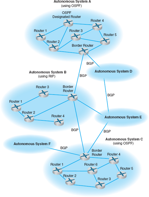
FIGURE 5.11 Routing on the Internet with Border Gateway Protocol (BGP), Open Shortest Path First (OSPF), and Routing Information Protocol (RIP)
Routing Information Protocol (RIP) is a dynamic distance vector interior routing protocol that is commonly used in smaller networks, such as those operated by one organization. The network manager uses RIP to develop the routing table. When new computers are added, RIP simply counts the number of computers in the possible routes to the destination and selects the route with the least number. Computers using RIP send broadcast messages every minute or so (the timing is set by the network manager) announcing their routing status to all other computers. RIP is used by both TCP/IP and IPX/SPX.
Intermediate System to Intermediate System (IS-IS) is a link state interior routing protocol that is commonly used in large networks. IS-IS is an ISO protocol that has been added to many TCP/IP networks.
Open Shortest Path First (OSPF) is a dynamic hybrid interior routing protocol that is commonly used on the Internet. It uses the number of computers in a route as well as network traffic and error rates to select the best route. OSPF is more efficient than RIP because it normally doesn't use broadcast messages. Instead, it selectively sends status update messages directly to selected computers or routers. OSPF is the preferred interior routing protocol used by TCP/IP.
Enhanced Interior Gateway Routing Protocol (EIGRP) is a dynamic hybrid interior routing protocol developed by Cisco and is commonly used inside organizations. Hybrid means that it has some features that act like distance vector protocols and some other features that act like link-state protocols. As you might expect, EIGRP is an improved version of Interior Gateway Routing Protocol (IGRP). EIGRP records information about a route's transmission capacity, delay, reliability, and load. EIGRP is unique in that computer or routers store their own routing table as well as the routing tables for all of their neighbors so they have a more accurate understanding of the network.
5.5.3 Multicasting
The most common type of message in a network is the transmission between two computers. One computer sends a message to another computer (e.g., a client requesting a Web page). This is called a unicast message. Earlier in the chapter, we introduced the concept of a broadcast message that is sent to all computers on a specific LAN or subnet. A third type of message called a multicast message is used to send the same message to a group of computers.
Consider a videoconferencing situation in which four people want to participate in the same conference. Each computer could send the same voice and video data from its camera to the computers of each of the other three participants using unicasts. In this case, each computer would send three identical messages, each addressed to the three different computers. This would work but would require a lot of network capacity. Alternately, each computer could send one broadcast message. This would reduce network traffic (because each computer would send only one message), but every computer on the network would process it, distracting them from other tasks. Broadcast messages usually are transmitted only within the same LAN or subnet, so this would not work if one of the computers were outside the subnet.
5.2 CAPTAIN D'S GETS COOKING WITH MULTICAST
MANAGEMENT FOCUS
Captain D's has more than 500 company owned and franchised fast-food restaurants across North America. Each restaurant has a small low-speed satellite link that can send and receive data at speeds similar to broadband Internet access (384 Kbps to 1.2 Mbps).
Captain D's used to send its monthly software updates to each of its restaurants one at a time, which meant transferring each file 500 times, once to each restaurant. You don't have to be a network wizard to realize that this is slow and redundant.
Captain D's now uses multicasting to send monthly software updates to all its restaurants at once. What once took hours is now accomplished in minutes.
Multicasting also enables Captain D's to send large human resource file updates each week to all restaurants and to transmit computer-based training videos to all restaurants each quarter. The training videos range in size from 500–1000 megabytes, so without multicasting it would be impossible to use the satellite network to transmit the videos.
_________
SOURCE: “Captain D's Gets Cooking with Multicast from XcelleNet,” www.xcellenet.com, 2004.
The solution is multicast messaging. Computers wishing to participate in a multicast send a message to the sending computer or some other computer performing routing along the way using a special type of packet called Internet Group Management Protocol (IGMP). Each multicast group is assigned a special IP address to identify the group. Any computer performing routing knows to route all multicast messages with this IP address onto the subnet that contains the requesting computer. The routing computer sets the data link layer address on multicast messages to a matching multicast data link layer address. Each requesting computer must inform its data link layer software to process incoming messages with this multicast data link layer address. When the multicast session ends (e.g., the videoconference is over), the client computer sends another IGMP message to the organizing computer or the computer performing routing to remove it from the multicast group.
5.5.4 The Anatomy of a Router
There is a huge array of software and hardware that makes the Internet work, but the one device that is indispensable is the router. The router has three main functions: (1) it determines a path for a packet to travel over, (2) it transmits the packet across the path, and (3) it supports communication between wide variety of devices and protocols. Now we will look inside a router to see how these three functions are supported by hardware and software.
Routers are essentially special-purpose computers that consist of a CPU (central processing unit), memory (both volatile and non-volatile), and ports or interfaces that connect to them to the network and/or other devices so that a network administrator can communicate with them. What differentiates routers from computers that we use in our everyday lives is that they are diskless and they don't come with a monitor, keyboard, and mouse. They don't have these because they were designed to move data rather than display it.
There are three ways that a network manager can connect to a router and configure and maintain it: (1) console port, (2) network interface port, and (3) auxiliary port (see Figure 5.12). When the router is turned on for the very first time, it does not have an IP address assigned, so it cannot communicate on the network. Because of this, the console port, also called the management port, is used to configure it. A network manager would use a blue rollover cable (not the Ethernet cable) to connect the router's console port to a computer that has terminal emulation software on it. The network manager would use this software to communicate with the router and perform the basic set-up (e.g., IP address assignment, routing protocol selection). Once the basic set-up is done, the network manager can log in to the router from any computer using the network interface using TCP/IP and Telnet with Secure Shell (SSH). Although routers come with an auxiliary port that allows an administrator to log via a direct, non-network connection (e.g., using modems), this connection is rarely used today.
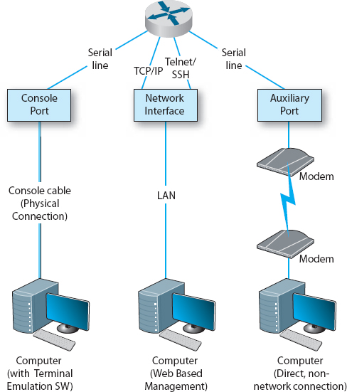
FIGURE 5.12 Anatomy of a router
A router, just like a computer, must have an operating system so that it can be configured. The operating system that is used in about 90% of routers is the Cisco Internetwork Operating Systems (IOS), although other operating systems exist too. IOS uses a command line interface rather than a graphical user interface. The network manager uses IOS commands to create a configuration file (also a config file) that defines how the router will operate. The config file can contain the type of routing protocol be used, the interfaces that are active/enabled and those that are down, and what type of encryption is used. The Config file is central to a router's operation and the IOS refers to it hundreds of times per second in order to tell the router how to do its job.
The other important file is the Access Control List (ACL), which plays an important role in network security. The ACL defines what types of packets should be routed and what types of packets should be discarded. The ACL is discussed in more detail in Chapter 10 on security.
5.6 TCP/IP EXAMPLE
This chapter has discussed the functions of the transport and network layers: linking to the application layer, segmenting, session management, addressing, and routing. In this section, we tie all of these concepts together to take a closer look at how these functions actually work using TCP/IP.
When a computer is installed on a TCP/IP network (or dials into a TCP/IP network), it must be given four pieces of network layer addressing and routing information before it can operate. This information can be provided by a configuration file, or via a DHCP server. The information is
- Its IP address
- A subnet mask, so it can determine what addresses are part of its subnet
- The IP address of a DNS server, so it can translate application layer addresses into IP addresses
- The IP address of an IP gateway (commonly called a router) leading outside of its subnet, so it can route messages addressed to computers outside of its subnet (this presumes the computer is using static routing and there is only one connection from it to the outside world through which all messages must flow; if it used dynamic routing, some routing software would be needed instead)
These four pieces of information are the minimum required. A server would also need to know its application layer address.
In this section, we use the simple network shown in Figure 5.13 to illustrate how TCP/IP works. This figure shows an organization that has four LANs connected by a BN. The BN also has a connection to the Internet. Each building is configured as a separate subnet. For example, Building A has the 128.192.98.x subnet, whereas Building B has the 128.192.95.x subnet. The BN is its own subnet: 128.192.254.x. Each building is connected to the BN via a router that has two IP addresses and two data link layer addresses, one for the connection into the building and one for the connection onto the BN. The organization has several Web servers spread throughout the four buildings. The DNS server and the router onto the Internet are located directly on the BN itself. For simplicity, we will assume that all networks use Ethernet as the data link layer and will only focus on Web requests at the application layer.
In the next sections, we describe how messages are sent through the network. For the sake of simplicity, we will initially ignore the need to establish and close TCP connections. Once you understand the basic concepts, we will then add these in to complete the example.
5.6.1 Known Addresses, Same Subnet
Let's start with the simplest case. Suppose that a user on a client computer in Building A (128.192.98.130) requests a Web page from the Web server in the same building (www1.anyorg.com). We will assume that this computer knows the network layer and data link layer addresses of the Web server (e.g., it has previously requested pages from this server, so the addresses are in its address tables). Because the application layer software knows the IP address of the server, it uses its IP address, not its application layer address.

FIGURE 5.13 Example Transmission Control Protocol/Internet Protocol (TCP/IP) network
5.3 FINDING YOUR COMPUTER'S TCP/IP SETTINGS
TECHNICAL FOCUS
If your computer can access the Internet, it must use TCP/IP. In Windows, you can find out your TCP/IP settings by looking at their properties. Click on the Start button and then select Control Panel and then select Network Connections. Double click on your Local Area Connection and then click the Support tab.
This will show you your computer's IP address, subnet mask, and gateway, and whether the IP address is assigned by a DHCP server. Figure 5.14 shows this information for one of our computers.
If you would like more information, you can click on the Details button. This second window shows the same information, plus the computer's Ethernet address (called the physical address), as well as information about the DHCP lease and the DNS servers available.
Try this on your computer. If you have your own home network with your own router, there is a chance that your computer has an IP address very similar to ours or someone else's in your class—or the same address, in fact. How can two computers have the same IP address? Well, they can't. This is a security technique called network address translation in which one set of “private” IP addresses is used inside a network and a different set of “public” IP addresses is used by the router when it sends the messages onto the Internet. Network address translation is described in detail in Chapter 11.

FIGURE 5.14 TCP/IP configuration information
In this case, the application layer software (i.e., Web browser) passes an HTTP packet containing the user request to the transport layer software requesting a page from 128.192.98.53. The transport layer software (TCP) would take the HTTP packet, add a TCP segment, and then hand it to the network layer software (IP). The network layer software will compare the destination address (128.192.98.53) to the subnet mask (255.255.255.0) and discover that this computer is on its own subnet. The network layer software will then search its data link layer address table and find the matching data link layer address (00-0C-00-33-3A-F2). The network layer would then attach an IP packet and pass it to the data link layer, along with the destination Ethernet address. The data link layer would surround the frame with an Ethernet frame and transmit it over the physical layer to the Web server (Figure 5.15).
The data link layer on the Web server would perform error checking before passing the HTTP packet with the TCP segment and IP packet attached to its network layer software. The network layer software (IP) would then process the IP packet, see that it was destined to this computer, and pass it to the transport layer software (TCP). This software would process the TCP segment, see that there was only one packet, and pass the HTTP packet to the Web server software.

FIGURE 5.15 Packet nesting. HTTP = Hypertext Transfer Protocol; IP = Internet Protocol; TCP = Transmission Control Protocol
The Web server software would find the page requested, attach an HTTP packet, and pass it to its transport layer software. The transport layer software (TCP) would break the Web page into several smaller segment, each less than 1,500 bytes in length, and attach a TCP segment (with a number to indicate the order) to each. Each smaller segment would then go to the network layer software, get an IP packet attached that specified the IP address of the requesting client (128.192.98.130), and be given to the data link layer with the client's Ethernet address (00-0C-00-33-3A-A3) for transmission. The data link layer on the server would transmit the frames in the order in which the network layer passed them to it.
The client's data link layer software would receive the frames, perform error checking, and pass the IP packets inside them to the network layer. The network layer software (IP) would check to see that the packets were destined for this computer and pass the TCP segments they contained to the transport layer software. The transport layer software (TCP) would assemble the separate segments, in order, back into one Web page, and pass the HTTP packet in turn to the Web browser to display on the screen.
5.6.2 Known Addresses, Different Subnet
Suppose this time that the same client computer wanted to get a Web page from a Web server located somewhere in Building B (www2.anyorg.com). Again, assume that all addresses are known and are in the address tables of all computers. In this case, the application layer software would pass an HTTP packet to the transport layer software (TCP) with the Internet address of the destination www2.anyorg.com: 128.192.95.30. The transport layer software (TCP) would make sure that the request fit in one segment and hand it to the network layer. The network layer software (IP) would then check the subnet mask and would recognize that the Web server is located outside of its subnet. Any messages going outside the subnet must be sent to the router (128.192.98.1), whose job it is to process the message and send the message on its way into the outside network. The network layer software would check its address table and find the Ethernet address for the router. It would therefore set the data link layer address to the router's Ethernet address on this subnet (00-0C-00-33-3A-0B) and pass the IP packet to the data link layer for transmission. The data link layer would add the Ethernet frame and pass it to the physical layer for transmission.
The router would receive the message and its data link layer would perform error checking and send an acknowledgement before passing the packet to the network layer software (IP). The network layer software would read the IP address to determine the final destination. The router would recognize that this address (128.192.95.30) needed to be sent to the 128.192.95.x subnet. It knows the router for this subnet is 128.192.254.5. It would pass the packet back to its data link layer, giving the Ethernet address of the router (00-0C-00-33-3A-AF).
This router would receive the message (do error checking, etc.) and read the IP address to determine the final destination. The router would recognize that this address (128.192.95.30) was inside its 128.192.95.x subnet and would search its data link layer address table for this computer. It would then pass the packet to the data link layer along with the Ethernet address (00-0C-00-33-3A-A0) for transmission.
The www2.anyorg.com web server would receive the message and process it. This would result in a series of TCP/IP packets addressed to the requesting client (128.192.98.130). These would make their way through the network in reverse order. The Web server would recognize that this IP address is outside its subnet and would send the message to the 128.192.95.5 router using its Ethernet address (00-0C-00-33-3A-B4). This router would then send the message to the router for the 128.192.98.x subnet (128.192.254.3) using its Ethernet address (00-0C-00-33-3A-BB). This router would in turn send the message back to the client (128.192.98.130) using its Ethernet address (00-0C-00-33-3A-A3).
This process would work in the same way for Web servers located outside the organization on the Internet. In this case, the message would go from the client to the 128.192.98.x router, which would send it to the Internet router (128.192.254.7), which would send it to its Internet connection. The message would be routed through the Internet, from router to router until it reached its destination. Then the process would work in reverse to return the requested page.
5.6.3 Unknown Addresses
Let's return to the simplest case (requesting a Web page from a Web server on the same subnet), only this time we will assume that the client computer does not know the network layer or data link layer address of the Web server. For simplicity, we will assume that the client knows the data link layer address of its subnet router, but after you read through this example, you will realize that obtaining the data link layer address of the subnet router is straightforward. (It is done the same way as the client obtains the data link layer address of the Web server.)
Suppose the client computer in Building A (128.192.98.130) wants to retrieve a Web page from the www1.anyorg.com Web server but does not know its addresses. The Web browser realizes that it does not know the IP address after searching its IP address table and not finding a matching entry. Therefore, it issues a DNS request to the name server (128.192.254.4). The DNS request is passed to the transport layer (TCP), which attaches a UDP datagram and hands the message to the network layer.
Using its subnet mask, the network layer (IP) will recognize that the DNS server is outside of its subnet. It will attach an IP packet and set the data link layer address to its router's address.
The router will process the message and recognize that the 128.192.254.4 IP address is on the BN. It will transmit the packet using the DNS server's Ethernet address.
The name server will process the DNS request and send the matching IP address back to the client via the 128.198.98.x subnet router.
The IP address for the desired computer makes its way back to the application layer software, which stores it in its IP table. It then issues the HTTP request using the IP address for the Web server (128.192.98.53) and passes it to the transport layer, which in turn passes it to the network layer. The network layer uses its subnet mask and recognizes that this computer is on its subnet. However, it does not know the Web server's Ethernet address. Therefore, it broadcasts an ARP request to all computers on its subnet, requesting that the computer whose IP address is 128.192.98.53 to respond with its Ethernet address.
This request is processed by all computers on the subnet, but only the Web server responds with an ARP packet giving its Ethernet address. The network layer software on the client stores this address in its data link layer address table and sends the original Web request to the Web server using its Ethernet address.
This process works the same for a Web server outside the subnet, whether in the same organization or anywhere on the Internet. If the Web server is far away (e.g., Australia), the process will likely involve searching more than one name server, but it is still the same process.
5.6.4 TCP Connections
Whenever a computer transmits data to another computer, it must choose whether to use a connection-oriented service via TCP or a connectionless service via UDP. Most application layer software such as Web browsers (HTTP), email (SMTP), FTP, and Telnet use connection-oriented services. This means that before the first packet is sent, the transport layer first sends a SYN segment to establish a session. Once the session is established, then the data packets begin to flow. Once the data are finished, the session is closed with a FIN segment.
In the preceding examples, this means that the first packet sent is really a SYN segment, followed by a response from the receiver accepting the connection, and then the packets as described above. There is nothing magical about the SYN and FIN segments, they are addressed and routed in the same manner as any other packets. But they do add to the complexity and length of the example.
A special word is needed about HTTP packets. When HTTP was first developed, Web browsers opened a separate TCP session for each HTTP request. That is, when they requested a page, they would open a session, send the single packet requesting the Web page, and close the session at their end. The Web server would open a session, send as many packets as needed to transmit the requested page, and then close the session. If the page included graphic images, the Web browser would open and close a separate session for each request. This requirement to open and close sessions for each request was time consuming and not really necessary. With the newest version of HTTP, Web browsers open one session when they first issue an HTTP request and leave that session open for all subsequent HTTP requests to the same server.
5.6.5 TCP/IP and Network Layers
In closing this chapter, we want to return to the layers in the network model and take another look at how messages flow through the layers. Figure 5.16 shows how a Web request message from a client computer in Building A would flow through the network layers in the different computers and devices on its way to the server in Building B.
The message starts at the application layer of the sending computer (the client in Building A), shown in the upper left corner of the figure, which generates an HTTP packet. This packet is passed to the transport layer, which surrounds the HTTP packet with a TCP segment. This is then passed to the network layer, which surrounds it with an IP frame that includes the IP address of the final destination (128.192.95.30). This in turn is passed to the data link layer, which surrounds it within an Ethernet frame that also includes the Ethernet address of the next computer to which the message will be sent (00-0C-00-33-3A-0B). Finally, this is passed to the physical layer, which converts it into electrical impulses for transmission through the cable to its next stop—the router that serves as the gateway in Building A.
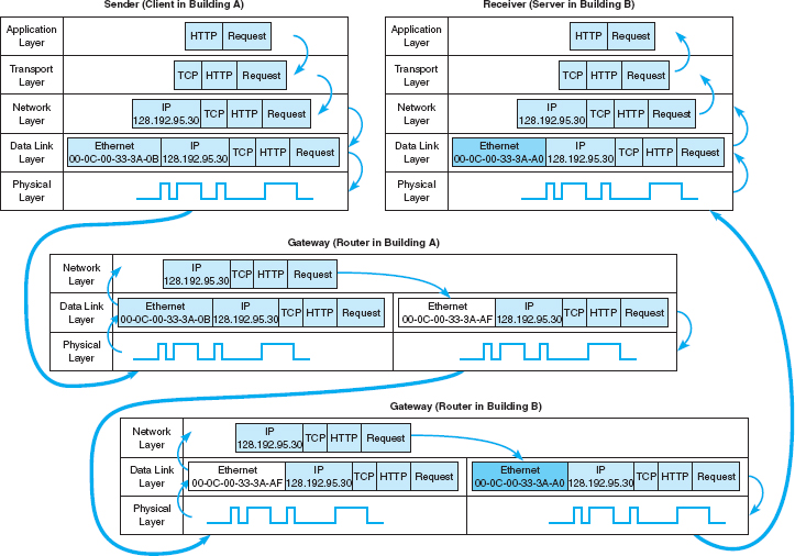
FIGURE 5.16 How messages move through the network layers Note: The addresses in this example are destination addresses
When the message arrives at the router in Building A, its physical layer translates it from electrical impulses into digital data and passes the Ethernet frame to the data link layer. The data link layer checks to make sure that the Ethernet frame is addressed to the router, performs error detection, strips off the Ethernet frame, and passes its contents (the IP packet) to the network layer. The routing software running at the network layer looks at the destination IP address, determines the next computer to which the packet should be sent, and passes the outgoing packet down to the data link layer for transmission. The data link layer surrounds the IP packet with a completely new Ethernet frame that contains the destination address of the next computer to which the packet will be sent (00-0C-00-33-3A-AF). In Figure 5.16, this new frame is shown in a different color. This is then passed to the physical layer, which transmits it through the network cable to its next stop—the router that serves as the gateway in Building B.
When the message arrives at the router in Building B, it goes through the same process. The physical layer passes the incoming packet to the data link layer, which checks the destination Ethernet address, performs error detection, strips off the Ethernet frame, and passes the IP packet to the network layer software. The software determines the next destination and passes the IP packet back to the data link layer, which adds a completely new Ethernet frame with the destination address of its next stop (00-0C-00-33-3A-A0)—its final destination.
The physical layer at the server receives the incoming packet and passes it to the data link layer, which checks the Ethernet address, performs error detection, removes the Ethernet frame, and passes the IP packet to the network layer. The network layer examines the final destination IP address on the incoming packet and recognizes that the server is the final destination. It strips off the IP packet and passes the TCP segment to the transport layer, which in turn strips off the TCP segment and passes the HTTP packet to the application layer (the Web server software).
There are two important things to remember from this example. First, at all gateways (i.e., routers) along the way, the packet moves through the physical layer and data link layer up to the network layer, but no higher. The routing software operates at the network layer, where it selects the next computer to which the packet should be sent, and passes the packet back down through the data link and physical layers. These three layers are involved at all computers and devices along the way, but the transport and application layers are only involved at the sending computer (to create the application layer packet and the TCP segment) and at the receiving computer (to understand the TCP segment and process the application layer packet). Inside the TCP/IP network itself, messages only reach layer three—no higher.
Second, at each stop along the way, the Ethernet frame is removed and a new one is created. The Ethernet frame lives only long enough to move the message from one computer to the next and then is destroyed. In contrast, the IP packet and the packets above it (TCP and application layer) never change while the message is in transit. They are created and removed only by the original message sender and the final destination.
5.4 PODCASTING
TECHNICAL FOCUS
Podcasting is the distribution of audio and video files (e.g., MP3 files) over the Internet. Podcasting uses a relatively old technology (first developed in 2000), but became popular with the introduction of Apple's iPod.
Podcasting requires two things: the content and a channel description file that describes the content. The content is usually MP3 files, audio and/or video. Creating MP3 files is fairly straightforward—see the Hands-On Activity in Chapter 3.
The channel description file describes the overall set of files, called a channel, as well as each individual MP3 file that is available. This file is an XML file that is created according to the RSS standard (RSS stands for Rich Site Summary, RDF Site Summary, or Really Simple Syndication, depending upon which version of the standard you read).
Users subscribe to a podcast channel by entering the URL of the channel description RSS file into their favorite aggregation software (e.g., iTunes). The aggregation software regularly reads the RSS file. When it notices that the RSS file contains a new entry for a new MP3 file, the software automatically downloads the new content to the user's iPod.
5.7 IMPLICATIONS FOR MANAGEMENT
The implications from this chapter are similar in many ways to the implications from Chapter 4. There used to be several distinct protocols used at the network and transport layers but as the Internet has become an important network, most organizations are moving to the adoption of TCP/IP as the single standard protocol at the transport and network layers. This is having many of the same effects described in Chapter 4: The cost of buying and maintaining networking equipment and the cost of training networking staff is steadily decreasing. However, as we move closer to running out of IPv4 addresses, more organizations will move to IPv6. This will cost a lot, but most organizations will see little business value from the change.
As TCP/IP becomes the dominant transport and network layer protocol for digital data, telephone companies who operate large non-TCP/IP-based networks to carry voice traffic are beginning to wonder whether they too should make the switch to TCP/IP. This has significant financial implications for companies that manufacture large networking equipment used in these networks.
SUMMARY
Transport and Network Layer Protocols TCP/IP are the standard transport and network protocols used today. They perform addressing (finding destination addresses), routing (finding the “best” route through the network), and segmenting (breaking large messages into smaller packets for transmission and reassembling them at the destination).
Transport Layer The transport layer (TCP) uses the source and destination port addresses to link the application layer software to the network. TCP is also responsible for segmeting—breaking large messages into smaller segments for transmission and reassembling them at the receiver's end. When connection-oriented routing is needed, TCP establishes a connection or session from the sender to the receiver. When connectionless routing is needed, TCP is replaced with UDP. Quality of service provides the ability to prioritize packets so that real-time voice packets are transmitted more quickly than simple email messages.
Addressing Computers can have three different addresses: application layer address, network layer address, and data link layer address. Data link layer addresses are usually part of the hardware, whereas network layer and application layer addresses are set by software. Network layer and application layer addresses for the Internet are assigned by Internet registrars. Addresses within one organization are usually assigned so that computers in the same LAN or subnet have similar addresses, usually with the same first 3 bytes. Subnet masks are used to indicate whether the first 2 or 3 bytes (or partial bytes) indicate the same subnet. Some networks assign network layer addresses in a configuration file on the client computer whereas others use dynamic addressing in which a DHCP server assigns addresses when a computer first joins the network.
Address Resolution Address resolution is the process of translating an application layer address into a network layer address or translating a network layer address into a data link layer address. On the Internet, network layer resolution is done by sending a special message to a DNS server (also called a name server) that asks for the IP address (e.g., 128.192.98.5) for a given Internet address (e.g., www.kelley.indiana.edu). If a DNS server does not have an entry for the requested Internet address, it will forward the request to another DNS server that it thinks is likely to have the address. That server will either respond or forward the request to another DNS server, and so on, until the address is found or it becomes clear that the address is unknown. Resolving data link layer addresses is done by sending an ARP request in a broadcast message to all computers on the same subnet that asks the computer with the requested IP address to respond with its data link layer address.
Routing Routing is the process of selecting the route or path through the network that a message will travel from the sending computer to the receiving computer. With centralized routing, one computer performs all the routing decisions. With static routing, the routing table is developed by the network manager and remains unchanged until the network manager updates it. With dynamic routing, the goal is to improve network performance by routing messages over the fastest possible route; an initial routing table is developed by the network manager but is continuously updated to reflect changing network conditions, such as message traffic. BGP, RIP, ICMP, EIGRP, and OSPF are examples of dynamic routing protocols.
TCP/IP Example In TCP/IP, it is important to remember that the TCP segments and IP packets are created by the sending computer and never change until the message reaches its final destination. The IP packet contains the original source and ultimate destination address for the packet. The sending computer also creates a data link layer frame (e.g., Ethernet) for each message. This frame contains the data link layer address of the current computer sending the packet and the data link layer address of the next computer in the route through the network. The data link layer frame is removed and replaced with a new frame at each computer at which the message stops as it works its way through the network. Thus, the source and destination data link layer addresses change at each step along the route whereas the IP source and destination addresses never change.
KEY TERMS
Access Control List (ACL)
address resolution
Address Resolution Protocol (ARP)
addressing
application layer address
autonomous systems
auxiliary port
Border Gateway Protocol (BGP)
border router
broadcast message
centralized routing
Cisco IOS
classless addressing
connectionless messaging
connection-oriented messaging
console port
data link layer address
designated router
destination port address
distance vector dynamic routing
Domain Name Service (DNS)
dynamic addressing
Dynamic Host Configuration Protocol (DHCP)
dynamic routing
Enhanced Interior Gateway Routing Protocol (EIGRP)
exterior routing protocol
gateway
hop
Intermediate System to Intermediate System (IS-IS)
Interior Gateway Routing Protocol (IGRP)
interior routing protocol
Internet address classes
Internet Control Message Protocol (ICMP)
Internet Corporation for Assigned Names and Numbers (ICANN)
Internet Group Management Protocol (IGMP)
link state dynamic routing
multicast message
name server
Network Interface port (TCP/IP port)
network layer address
Open Shortest Path First (OSPF)
port address
Quality of Service (QoS)
Real-Time Streaming Protocol (RTSP)
RSS
Real-Time Transport Protocol (RTP)
Resource Reservation Protocol (RSVP)
router
routing
Routing Information Protocol (RIP)
routing table
segment
segmenting
source port address
static routing
subnet
subnet mask
Transmission Control Protocol/Internet Protocol (TCP/IP)
unicast message
User Datagram Protocol (UDP)
QUESTIONS
- What does the transport layer do?
- What does the network layer do?
- What are the parts of TCP/IP and what do they do? Who is the primary user of TCP/IP?
- Compare and contrast the three types of addresses used in a network.
- How is TCP different from UDP?
- How does TCP establish a session?
- What is a subnet and why do networks need them?
- What is a subnet mask?
- How does dynamic addressing work?
- What benefits and problems does dynamic addressing provide?
- What is address resolution?
- How does TCP/IP perform address resolution from URLs into network layer addresses?
- How does TCP/IP perform address resolution from IP addresses into data link layer addresses?
- What is routing?
- How does decentralized routing differ from centralized routing?
- What are the differences between connectionless and connection-oriented messaging?
- What is a session?
- What is QoS routing and why is it useful?
- Compare and contrast unicast, broadcast, and multicast messages.
- Explain how multicasting works.
- Explain how the client computer in Figure 5.14 (128.192.98.xx) would obtain the data link layer address of its subnet router.
- Why does HTTP use TCP and DNS use UDP?
- How does static routing differ from dynamic routing? When would you use static routing? When would you use dynamic routing?
- What type of routing does a TCP/IP client use? What type of routing does a TCP/IP gateway use? Explain.
- What is the transmission efficiency of a 10-byte Web request sent using HTTP, TCP/IP, and Ethernet? Assume the HTTP packet has 100 bytes in addition to the 10-byte URL. Hint: Remember from Chapter 4 that efficiency = user data/total transmission size.
- What is the transmission efficiency of a 1,000-byte file sent in response to a Web request HTTP, TCP/IP, and Ethernet? Assume the HTTP packet has 100 bytes in addition to the 1,000-byte file. Hint: Remember from Chapter 4 that efficiency = user data/total transmission size.
- What is the transmission efficiency of a 5,000-byte file sent in response to a Web request HTTP, TCP/IP, and Ethernet? Assume the HTTP packet has 100 bytes in addition to the 5,000-byte file. Assume that the maximum packet size is 1,200 bytes. Hint: Remember from Chapter 4 that efficiency = user data/total transmission size.
- Describe the anatomy of a router. How does a router differ from a computer?
EXERCISES
5-1. Would you recommend dynamic addressing for your organization? Why?
5-2. Look at your network layer software (either on a LAN or dial-in) and see what options are set—but don't change them! You can do this by using the RUN command to run winipcfg. How do these match the fundamental addressing and routing concepts discussed in this chapter?
5-3. Suppose a client computer (128.192.95.32) in Building B in Figure 5.13 requests a large Web page from the server in Building A (www1.anyorg.com). Assume that the client computer has just been turned on and does not know any addresses other than those in its configuration tables. Assume that all gateways and Web servers know all network layer and data link layer addresses.
- Explain what messages would be sent and how they would flow through the network to deliver the Web page request to the server.
- Explain what messages would be sent and how they would flow through the network as the Web server sent the requested page to the client.
- Describe, but do not explain in detail, what would happen if the Web page contained several graphic images (e.g., GIF [Graphics Interchange Format] or JPEG files).
5-4. Network Solutions provides a service to find who owns domain names and IP addresses. Go to www.networksolutions.com/whois. Find the owner of
5-5. What is the subnet portion of the IP address and what is the subnet mask for the following:
- 12.1.0.0/16
- 12.1.0.0/24
- 12.1.0.0/20
- 12.1.0.0/28
5-6. Complete the puzzle (which covers material from Chapters 2 through 5) on the next page.
MINI-CASES
I. Fred's Donuts
Fred's Donuts is a large regional bakery company that supplies baked goods (e.g., donuts, bread, pastries) to cafeterias, grocery stores, and convenience stores in three states. The company has five separate bakeries and office complexes spread over the region and wants to connect the five locations. Unfortunately, the network infrastructure at the five locations has grown up separately and thus there are two different network/transport layer protocols in use (TCP/IP and SPX/IPX). Should the company continue to use the two different protocols or move to one protocol, and if the latter, which one? Explain.
II. Central University
Suppose you are the network manager for Central University, a medium-sized university with 13,000 students. The university has 10 separate colleges (e.g., business, arts, journalism), 3 of which are relatively large (300 faculty and staff members, 2,000 students, and 3 buildings) and 7 of which are relatively small (200 faculty and staff, 1,000 students, and 1 building). In addition, there are another 2,000 staff members who work in various administration departments (e.g., library, maintenance, finance) spread over another 10 buildings. There are 4 residence halls that house a total of 2,000 students. Suppose the university has the 128.100.xxx.xxx address range on the Internet. How would you assign the IP addresses to the various subnets? How would you control the process by which IP addresses are assigned to individual computers? You will have to make some assumptions to answer both questions, so be sure to state your assumptions.
III. Connectus
Connectus is a medium-sized Internet Service Provider (ISP) that provides Internet access and data communication services to several dozen companies across the United States and Canada. Connectus provides fixed data connections for clients’ offices in about 50 cities and an internal network that connects them. For reliability purposes, all centers are connected with at least two other centers so that if one connection goes down, the center can still communicate with the network. Predicting access volume is difficult because it depends on how many sales representatives are in which city. Connectus currently uses RIP as its routing protocol, but is considering moving to OSPF. Should it stay with RIP or move to OSPF? Why?

Old Army is a large retail store chain operating about 1,000 stores across the United States and Canada. Each store is connected into the Old Army data network, which is used primarily for batch data transmissions. At the end of each day, each store transmits sales, inventory, and payroll information to the corporate head office in Atlanta. The network also supports email traffic, but its use is restricted to department managers and above. Because most traffic is sent to and from the Atlanta headquarters, the network is organized in a hub and spoke design. The Atlanta office is connected to 20 regional data centers, and each regional center is in turn connected to the 30–70 stores in its region. Network volumes have been growing, but at a fairly predictable rate as the number of stores and overall sales volume increases. Old Army currently uses RIP as its routing protocol, but is considering moving to OSPF. Should it stay with RIP or move to OSPF? Why?
V. General Stores
General Stores is a large retail store chain operating about 1,300 stores across the United States and Canada. Each store is connected into the corporate data network. At the end of each day, each store transmits sales and payroll information to the corporate head office in Seattle. Inventory data are transmitted in real time as products are sold to one of a dozen regional distribution centers across North America. The network is also used for credit card validations as customers check out and pay for their purchases. The network supports email traffic, but its use is restricted to department managers and above. The network is designed much like the Internet: One connection from each store goes into a regional network that typically has a series of network connections to other parts of the network. Network volumes have been growing, but at a fairly predictable rate as the number of stores and overall sales volume increases. General Stores is considering implementing a digital telephone service that will allow it to transmit internal telephone calls to other General Stores offices or stores through the data network. Telephone services outside of General Stores will continue to be done normally. General Stores currently uses RIP as its routing protocol, but is considering moving to OSPF. Should it stay with RIP or move to OSPF? Why?
CASE STUDY
NEXT-DAY AIR SERVICE
See the Web site.
HANDS-ON ACTIVITY 5A
Using TCP/IP
In this chapter, we've discussed the basic components of TCP/IP such as IP addresses, subnet masks, DNS requests, and ARP requests. In this activity, we'll show you how to explore these items on your computer. Although this activity is designed for Windows computers, most of these commands will also work on Apple computers.
This activity will use the command prompt, so start by clicking START, then RUN, and then type CMD and press enter. You should see the command window, which in Windows is a small window with a black background. Like all other windows you can change its shape by grabbing the corner and stretching it.
IPCONFIG: Reading your computer's settings
In a focus box earlier in the chapter, we showed you how to find your computer's TRCP/IP settings using Windows. You can also do it by using the IPCONFIG command. In the command window, type IPCONFIG/ALL and press enter.
You should see a screen like that shown in Figure 5.17. The middle of the screen will show the TCP/IP information about your computer. You can see the IP address (192.168.1.102 in Figure 5.17), the subnet mask (255.255.255.0), the default gateway, which is the IP address of the router leading out of your subnet (192.168.1.1), the DHCP server (192.168.1.1), and the available DNS servers (e.g., 63.240.76.4). Your computer will have similar, but different information. As discussed in Technical Focus 5.3, your computer might be using “private” IP addresses the same as my computer shown in Figure 5.17, so your addresses may be identical to mine. We'll explain how network address translation (NAT) is done in Chapter 10.
Deliverables
- Use the ipconfig/all command on your computer. What is the IP address, subnet mask, IP address of default gateway, and MAC of your computer?
- Why does every computer on the Internet need to have these four numbers?
PING: Finding other computers
The PING sends a small packet to any computer on the Internet to show you how long it takes the packet to travel from your computer to the target computer and back again. You can ping a computer using its IP address or Web URL. Not all computers respond to ping commands, so not every computer you ping will answer.
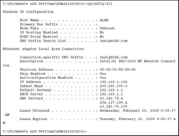
Start by pinging your default gateway: just type PING followed by the IP address of your gateway. Figure 5.18 shows that the PING command sends four packets to the target computer and then displays the maximum, minimum, and average transit times. In Figure 5.18, you can see that pinging my gateway is fast: less than one millisecond for the packet to travel from my computer to my router and back again.
Next, ping a well-known Web site in the United States to see the average times taken. Remember that not all Web sites will respond to the ping command. In Figure 5.18, you can see that it took an average of 52 milliseconds for a packet to go from my computer to Google and back again. Also note that www.google.com has an IP address of 216.239.37.99.
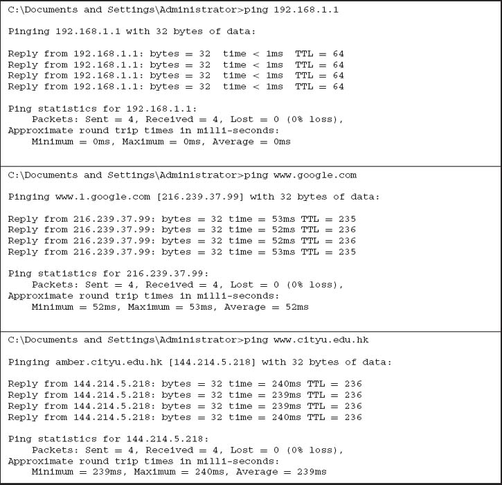
Now, ping a Web site outside the United States. In Figure 5.18, you can see that it took an average of 239 milliseconds for a packet to go from my computer to the City University of Hong Kong and back again. If you think about it, the Internet is amazingly fast.
Deliverables
- Ping your own default gateway. How many packets were returned? How long did it take for you default gateway to respond?
- Ping google.com. How many packets were returned? How long did it take for you default gateway to respond?
- Ping National Australian University www.anu. edu.au. How many packets were returned? How long did it take for you default gateway to respond?
ARP: Displaying Physical Addresses
Remember that in order to send a message to other computers on the Internet, you must know the physical address (aka data link layer address) of the next computer to send the message to. Most computers on the Internet will be outside your subnet, so almost all messages your computer sends will be sent to your gateway (i.e., the router leaving your subnet). Remember that computers use ARP requests to find physical addresses and store them in their ARP table. To find out what data link layer addresses your computer knows, you can use the ARP command.
At the command prompt, type ARP-A and press enter. This will display the contents of your ARP table. In Figure 5.19, you can see that the ARP table in my computer has only one entry, which means all the messages from my computer since I turned it on have only gone to this one computer—my router. You can also see the physical address of my router: 00-04-5a-0b-d1-40.
If you have another computer on your subnet, ping it and then take a look at your ARP table again. In Figure 5.19, you can see the ping of another computer my subnet (192.168.1.152) and then see the ARP table with this new entry. When I pinged 192.168.1.152, my computer had to find its physical address, so it issued an ARP request and 192.168.1.152 responded with an ARP response, which my computer added into the ARP table before sending the ping.
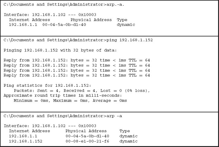
Deliverables
- Type ARP-A at the command prompt. What are the entries in your ARP table?
- Suppose, that there are no entries in your ARP table. Is this a problem? Why or why not?
NSLOOKUP: Finding IP Addresses
Remember that in order to send a message to other computers on the Internet, you must know their IP addresses. Computers use DNS servers to find IP addresses. You can issue a DNS request by using the NSLOOKUP command.
Type NSLOOKUP and the URL of a computer on the Internet and press enter. In Figure 5.20, you'll see that www.cnn.com has several IP addresses and is also known as cnn.com
Deliverable
Find the IP address of google.com and of another website of your choice.
DNS Cache
The IPCONFIG/DISPLAYDNS command can be used to show the contents of the DNS cache. You can experiment with this by displaying the cache, visiting a new Web site with your browser, and then displaying the cache again. Figure 5.21 shows part of the cache on my computer after visiting a number of sites. The DNS cache contains information about all the Web sites I've visited, either directly or indirectly (by having a Web page on one server pull a graphics file off of a different server).
For example, the second entry in this figure is ns1. cisco.com, which has an IP address of 128.107.241.185 (a 4-byte long address). The record type is one, which means this is a “host”—that is, a computer on the Internet using IPv4. Because the DNS information might change, all entries have a maximum time to live set by the DNS that provides the information (usually 24 hours); the time to live value is the time in seconds that this entry will remain in the cache until it is removed.
The very last entry in this figure is for ns1.v6. telekom.at. The record type of 28 means that this is a host that uses IPv6, which you can see from the 16-byte long address in the record (2001:890:600:d1::100).
Deliverables
- Display your DNS cache using the command ipconfig/displaydns.
- How many entries are there in your cache?
- Open your browser and visit www.ietf.com. Once the page loads, display your DNS cache again. Copy the DNS entry entry for this website.
TRACERT: Finding Routes through the Internet
The TRACERT command will show you the IP addresses of computers in the route from your computer to another computer on the Internet. Many networks have disabled TRACERT for security reasons, so it doesn't always work. Type TRACERT and the URL of a computer on the Internet and press enter. In Figure 5.22, you'll see the route from my computer, through the Insight network, through the AT&T network, through the Level 3 network, and then through the Google network until it reaches the server. TRACERT usually sends three packets, so beside each hop is the total time to reach that hop for each of the three packets. You'll see that it took just over 50 ms for a packet to go from my computer to Google. You'll also see that the times aren't always “right,” in that the first packet took 50 ms to reach the bbrl Washington Level 3 router (step 9) but only 40 ms to reach the next hop to the car2 Washington Level 3 router (step 10). The time to each hop is measured separately, each with a different packet, so sometimes a packet is delayed longer on one hop or another.
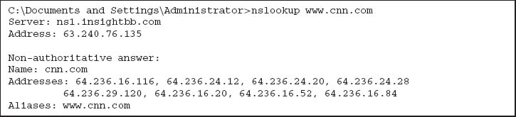
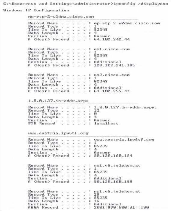

Deliverables
- Type tracert google.com in your comand window.
- How many computers/hops did it take the packet to reach google?
- What was the shortest hop (in terms of time)? Why do you think this is the shortest hop?
HANDS-ON ACTIVITY 5B
Exploring DNS Request and DNS Response
In this chapter, we talked about address resolution. This activity will help you see how your computer sends a DNS request for a website you never visited, before it can create a HTTP request packet to display the website on your browser. We will use Wireshark for this activity. Use of Wireshark was explained in Chapter 2.
- Use ipconfig/all command to find the IP address of your computer and your DNS server.
- So that we can explore the DNS request and response properly, the first step is to empty your DNS cache. Use ipconfig/flushdns command in the command prompt window to empty the DNS of your computer.
- Open Wireshark and enter “ip.addr==your IP address” into the filter to only capture packets that either originate or are destined for your computer.
- Start packet capture in Wireshark.
- With your browser, visit http://www.ietf.org.
- Stop packet capture after webpage is loaded.
Deliverables
- Locate the DNS query and response message for www.ietf.org. In Figure 5.23, they are packets 27 and 28. Are these packets sent over UDP or TCP?

- What is the destination port for the DNS query message? What is the source port of the DNE response message?
- To what IP address is the DNS query message sent? Compare this IP address to your local DNS server IP address. Are these two IP addresses the same?
- The www.ietf.org contains several images. Before retrieving each image, does your host issue a new DNS query? Why or why not?
- Now locate the HTTP Get message. What is the source and destination IP address? Compare the source to your IP address. Are these the same?
- Approximately how many HTTP GET request messages did your browser send? Why was there a need to send additional HTTP GET messages?
1 One way to make a Web server private would be to use a different port number (e.g., 8080). Any Web browser wanting to access this Web server would then have to explicitly include the port number in the URL (e.g., http://www.abc.com:8080).
2 If you ever want to find out the IP address of any computer, simply enter the command ping, followed by the application layer name of the computer at the command prompt (e.g., ping www.indiana.edu).
3 DNS requests and responses are usually short, so they use UDP as their transport layer protocol. That is, the DNS request is passed to the transport layer, which surrounds them in a UDP datagram before handing it to the network layer.
4 This is called recursive DNS resolution. DNS servers can also use iterative DNS resolution, whereby the client is told that the DNS server does not know the desired address but is given the IP address of another DNS server that can be used to find the address. The client then issues a new DNS request to that DNS server.
5 It would be reasonable at this point to guess that because ARP requests and responses are small, they use UDP in the same way that DNS requests and responses do. But they don't. Instead, ARP packets replace both TCP/UDP and IP and are placed directly into the data link layer frame with no transport or network layer PDUs.
6 If you ever want to find out the route through the Internet from your computer to any other computer on the Internet, simply enter the command tracert followed by the application layer name of the computer at the command line (e.g., tracert www.indiana.edu).
7 ICMP is the protocol used by the ping command.